Real-time monitoring method of pressure center load of wing based on strain actually measured through fiber grating

A fiber grating, measured strain technology, applied in the direction of measuring force components, measuring devices, using optical devices, etc., can solve problems such as the inability to realize long-term, real-time online monitoring of aircraft, the inability to service aircraft calibration, and the complexity of measuring equipment, etc. The effect of strong anti-electromagnetic interference ability, small size and simple method

Inactive Publication Date: 2017-11-28
BEIHANG UNIV
View PDF4 Cites 8 Cited by
  • Summary
  • Abstract
  • Description
  • Claims
  • Application Information

AI Technical Summary

Problems solved by technology

At present, my country has not realized the long-term, real-time online monitoring of the equivalent load of the pressure center position of the wing of the aircraft in service. The existing method of wing load research is based on the monitoring method of strain gauges. This method only Short-term m

Method used


Image

  • Real-time monitoring method of pressure center load of wing based on strain actually measured through fiber grating
  • Real-time monitoring method of pressure center load of wing based on strain actually measured through fiber grating
  • Real-time monitoring method of pressure center load of wing based on strain actually measured through fiber grating

Examples


Embodiment Construction

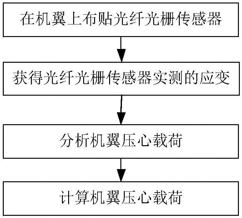
[0045] The present invention provides a real-time monitoring method of aircraft wing pressure center load based on fiber grating measured strain, see figure 1 As shown, it is realized through the following steps:

[0046] Step 1: Paste the fiber grating sensor on the wing

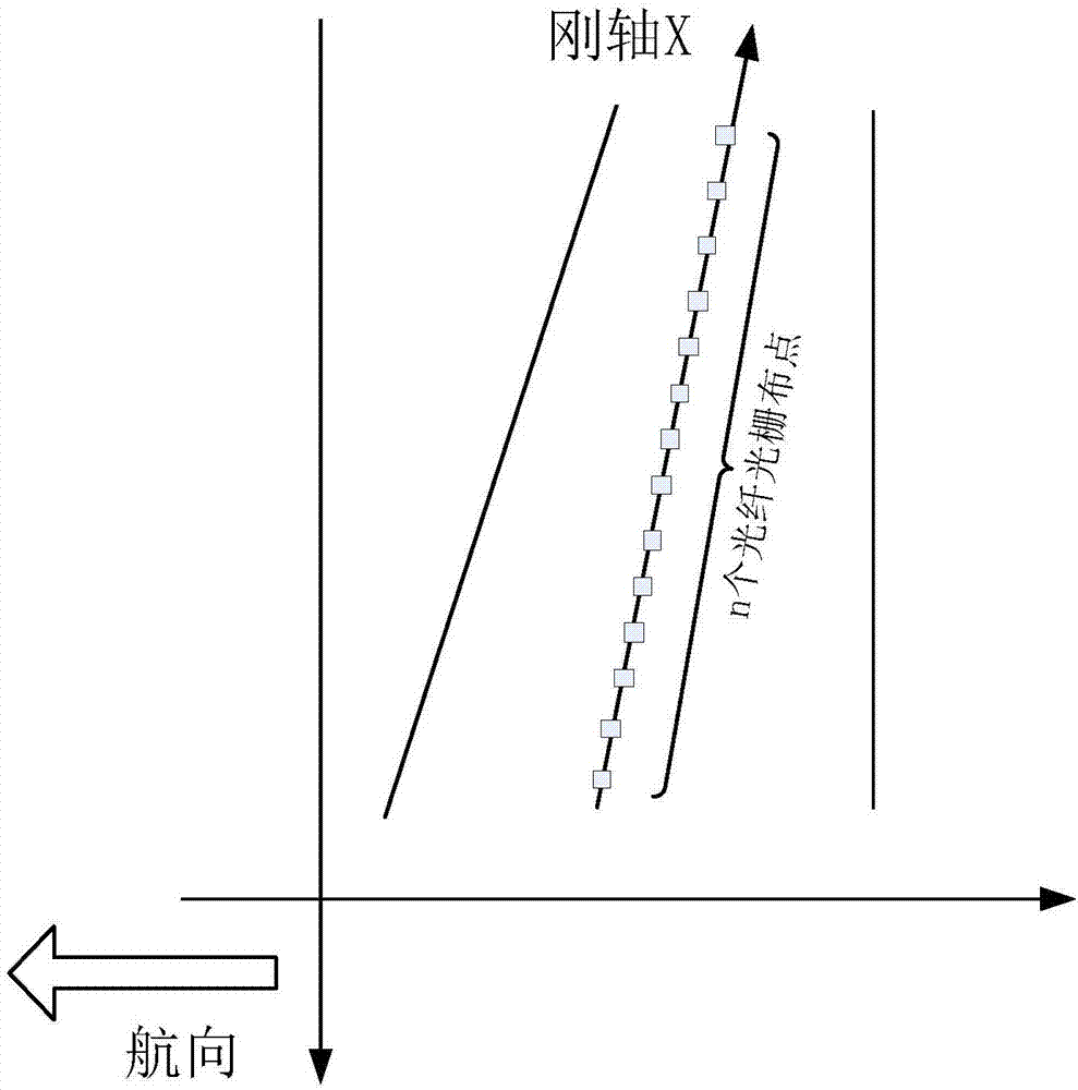
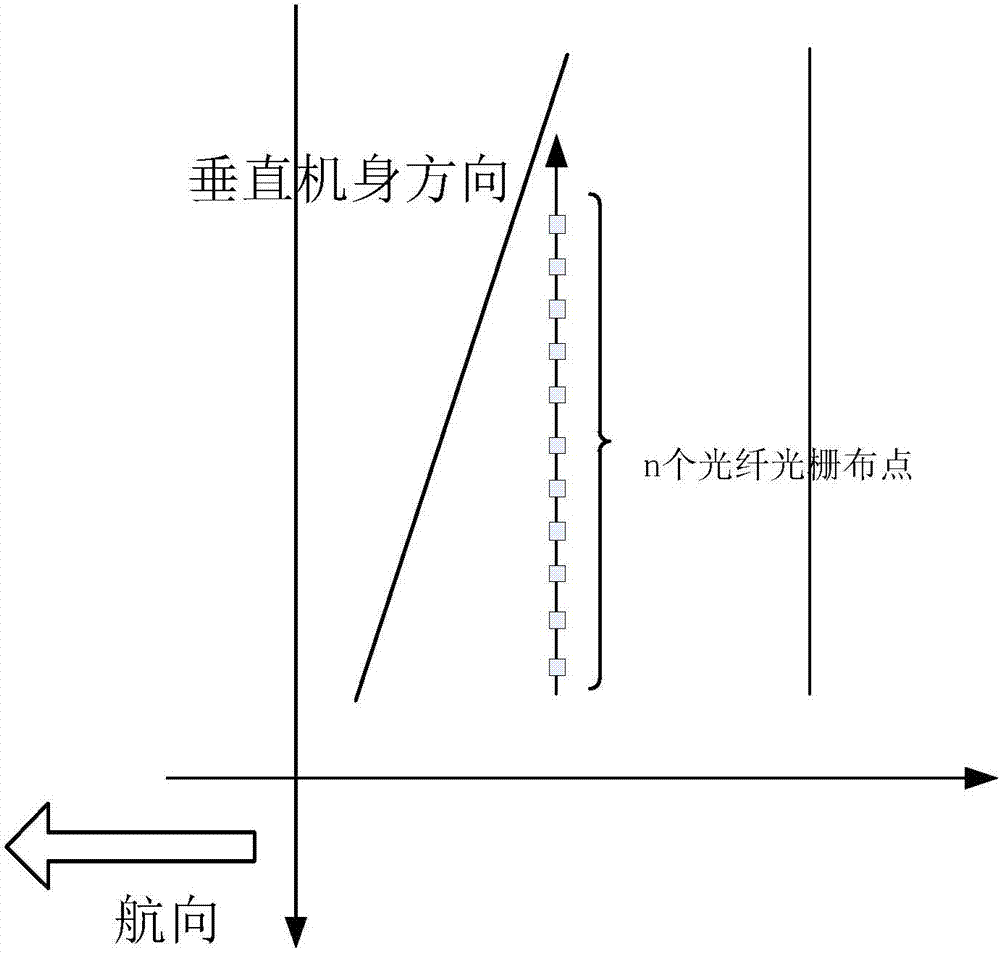
[0047] On the surface of the wing, deploy n points of fiber grating sensor measuring points along the direction of the rigid axis of the wing until it is close to the end of the wing, such as figure 2as shown; and, on the surface of the wing, deploy n points of FBG sensor measuring points along the direction perpendicular to the fuselage, and stick it to the end of the wing, such as image 3 shown;

[0048] Among them, no matter whether the fiber grating sensor is placed along the direction of the rigid axis of the wing or along the direction perpendicular to the fuselage, the position of the last one or several fiber grating sensor measuring points will be close to the position of the pressure center of...


PUM


Abstract

The invention provides a real-time monitoring method of pressure center load of a wing based on strain actually measured through a fiber grating. The method comprises following steps of 1, adhering a fiber grating sensor on the wing; 2, acquiring strain actually measured by the fiber grating sensor; 3, analyzing the pressure center load of the wing; and 4, calculating the pressure center load of the wing. In this way, by use of the strain data actually measured by the fiber grating adhered to the wing, the pressure center load of the wing is calculated, so the effect is achieved that the pressure center load of the wing can be acquired only by use of the strain data actually measured by the fiber grating without other information like wing load and the wind structure, so an actual problem is solved that real-time monitoring is performed on the pressure center load of the wing only based on the strain data actually measured by the fiber grating is solved.

Description

Technical field: [0001] The invention provides a method for real-time monitoring of wing pressure core load based on the measured strain of fiber grating, and specifically relates to obtaining the equivalent tension at the position of wing pressure core by using the measured strain measured by optical fiber grating, so as to realize the real-time monitoring of wing pressure core load. The monitoring is suitable for real-time monitoring of the pressure core load on the wing of the aircraft by using the measured strain measured by the fiber grating on the aircraft in service and in the aircraft fatigue test of the entire aircraft, and belongs to the technical field of test and measurement. Background technique: [0002] The wing of an aircraft is one of the important structural components of the aircraft and a key factor to ensure the safe flight of the aircraft. During the entire life cycle of the aircraft, the aircraft wing will experience a specific load history, which is a...

Claims


Application Information

Patent Timeline
IPC IPC(8): G01B11/16G01L5/16
CPCG01B11/165G01L5/16
Inventor 张卫方梁小贝魏巍刘晓鹏任飞飞李英武金博张萌
Owner BEIHANG UNIV
Why Eureka
Try Eureka