Storage system and data control method
A storage system and data technology, applied in the direction of electrical digital data processing, data processing input/output process, instruments, etc., to achieve the effect of prolonging life and reducing application management costs
- Summary
- Abstract
- Description
- Claims
- Application Information
AI Technical Summary
Problems solved by technology
Method used
Image

Examples
no. 1 approach
[0053] First Embodiment In a storage system equipped with only a semiconductor memory (SSD) as a storage device, by rearranging data between semiconductor memories with different characteristics (for example, between TLC and MLC), the life of the semiconductor memory is extended and the Lower cost of bits. Furthermore, by reallocating data among semiconductor memories of the same type (for example, between TLC and TLC), the load is distributed and the lifetime is increased.
[0054] (1-1) The overall structure of the computer system
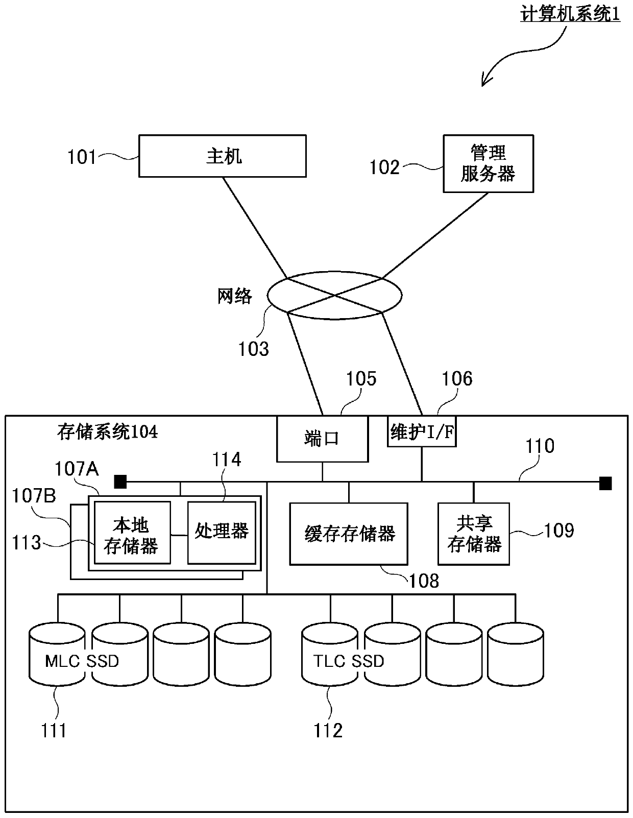
[0055] figure 1The overall configuration of the computer system 1 in the first embodiment is shown. The computer system 1 is composed of a host 101 , a management server 102 , a network 103 and a storage system 104 . The host 101 is, for example, a general server, and is connected to the port 105 of the storage system 104 via the network 103 . The host 101 sends a read request or a write request to the storage system 104 to read and write dat...
no. 2 approach
[0299] Second Embodiment In a storage system equipped with not only a semiconductor memory (SSD) but also a hard disk drive (HDD) as a storage device, the storage devices (SSD and HDD) are classified into levels according to performance, and access from the host is performed. It differs from the first embodiment in that the frequency of the hierarchical control that arranges the data in the storage device of the appropriate hierarchical level accordingly.
[0300] (2-1) The overall structure of the computer system
[0301] Figure 23 The overall configuration of the computer system 1A in the second embodiment is shown. The computer system 1A is equipped with an HDD (drive 2301) of the SAS (Serial Attached SCSI: Serial SCSI) specification, SSDs (drives 111 and 112) are set to layer 1, and an HDD (drive 2301) of the SAS specification is set to tier 1. The layer 2 differs from the first embodiment in that data is rearranged between layers according to the I / O frequency of each ...
no. 3 approach
[0346] In the third embodiment, the calculation of the write addable amount and the write reduction required amount described in the first embodiment ( Figure 8 )Methods. In the first embodiment, the write-addable rate and the write-reduction request rate are collected from the SSD, and they are used to calculate the above formulas 1 and 2 to calculate the write-addition amount and the write reduction request amount, but the SSD cannot directly In the case of collecting the write addable rate and the write reduction request rate, the write addable amount and the write reduction request amount can be calculated by the following method.
[0347] Figure 32 It shows the principle of acquiring the wear out indicator (Wear out Indicator) as life information of SSD, and calculating the amount of writing that can be added and the amount of writing reduction request based on the wear out indicator. The vertical axis of the graph is the wear index (lifetime rate) 3201 of the SSD, an...
PUM
 Abstract
Description
Claims
Application Information
 - R&D
- Intellectual Property
- Life Sciences
- Materials
- Tech Scout
- Unparalleled Data Quality
- Higher Quality Content
- 60% Fewer Hallucinations
Browse by: Latest US Patents, China's latest patents, Technical Efficacy Thesaurus, Application Domain, Technology Topic, Popular Technical Reports.
© 2025 PatSnap. All rights reserved.Legal|Privacy policy|Modern Slavery Act Transparency Statement|Sitemap|About US| Contact US: help@patsnap.com