
Small load-following nuclear power generation system using heat deformation of reflector caused by thermal expansion phenomenon

A technology of nuclear power generation and reflector, which can be used in nuclear power generation, nuclear power plants, and the conversion of reactor thermal energy into mechanical energy, etc., and can solve problems such as runaway nuclear reactions in the core

Active Publication Date: 2017-11-28
CLEAR
View PDF7 Cites 4 Cited by
  • Summary
  • Abstract
  • Description
  • Claims
  • Application Information

AI Technical Summary

Problems solved by technology

In such a large nuclear reactor using control rods, if the control rods cannot function due to failure of the position control mechanism of the control rods, etc., there is a danger of runaway nuclear reactions in the core

Method used


Image

  • Small load-following nuclear power generation system using heat deformation of reflector caused by thermal expansion phenomenon
  • Small load-following nuclear power generation system using heat deformation of reflector caused by thermal expansion phenomenon
  • Small load-following nuclear power generation system using heat deformation of reflector caused by thermal expansion phenomenon

Examples


Embodiment 1

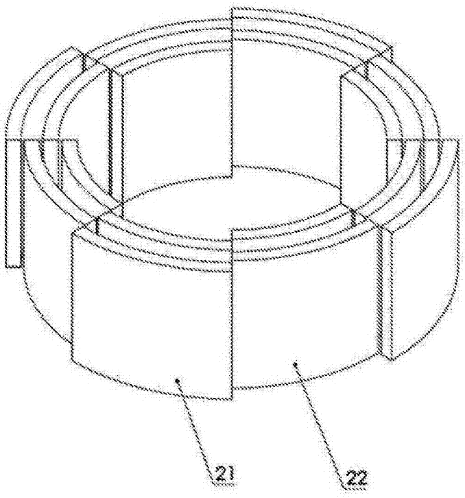
[0114] Next, refer to Figure 3A , 3B and Figure 4 , to illustrate the most important reflector in the load-following control of the present invention. Such as Figure 3A As shown, the reflector is formed of graphite and has a double structure with a thickness of 10 cm. This double structure is divided into eight parts in the circumferential direction, and each part is equipped with two kinds of reflectors A21 and B22 with different radii. When the circumferential direction is staggered, each other can be accommodated inside. Such as Figure 3B As shown, the dual structure of the reflector A21 and the reflector B22 is fixed by the reflector support plate 20 . The reflector B22 had an inner diameter of 52 cm and a height of 50 cm. By shifting such two types of reflectors with a double structure from each other, a gap (slit) can be formed between the reflector A21 and the reflector B22, thereby reducing the reflection efficiency. Carbon (for example, graphite carbon fine...

Embodiment 2

[0119] Next, it is explained that raising K eff Method for the temperature of the critical point of "1". Such as Figure 7 As shown, in addition to the reflector A21 and the reflector B22 divided into four parts, an overlapping part 23 is provided. This adjusts the width of the slit that occurs due to thermal expansion of the reflector. Figure 8 Indicates that the overlapping part of the reflector is set due to K eff Calculated results related to the width of the slit that occurs due to thermal expansion. according to Figure 8 It can be seen that K eff The temperature rise for =1 is about 500°C. In this way, in the split reflector, the K can be adjusted by adjusting the length of the overlapping portion eff =1 temperature.

Embodiment 3

[0121] Figure 9 Other examples of reflector structures of the present invention are shown. In Examples 1 and 2, split reflectors are arranged by providing slits between reflectors in the circumferential direction, thereby controlling K eff of. But in this embodiment, K is controlled by moving the reflector in the radial direction eff . Figure 9 describe its organization. In order to allow the double reflectors 21 and 22 divided into eight parts to separate from the fuel assembly as the temperature rises, the thermal expansion of the adjustment spring 26 is used. First, on the outer side of the double reflectors 21 and 22 divided into eight parts, a fixing cylinder 24 for fixing the adjustment spring 26 is arranged, and on the outer side, eight spring-driven jigs for moving the reflector are arranged corresponding to the divided reflectors. , the spring-driven jig for moving the reflector is formed by combining the adjustment spring support plate 27 , the reflector adjus...


PUM


Abstract

The present invention provides a small nuclear power generation system that allows easy load-following control, is safe, and is able to achieve reductions in production cost and costs for maintenance and management. The small nuclear power generation system is provided with a small reactor that adopts load-following control and that is provided with: a fuel assembly core 4 that uses metallic fuel containing one or both of uranium (235, 238) and plutonium-239; a reactor vessel 1 that houses the fuel assembly core 4; metallic sodium filled in the reactor vessel 1 and heated by the fuel assembly core 4; and a neutron reflector 2 that maintains the effective multiplication factor of neutrons emitted from the fuel assembly core 4 at approximately one or more to bring the core into a critical state, wherein a spring-shaped or spiral-shaped metallic member is coupled to the neutron reflector, and heat deformation of the metallic member due to the temperature of coolant metallic sodium is used to control fast neutron reflection efficiency of the neutron reflector to enable control of the effective multiplication factor of the neutrons.

Description

[0001] [Related Application] [0002] This application claims the priority of Japanese Patent Application No. 2015-75942 filed on April 2, 2015, the contents of which are incorporated herein by reference. technical field [0003] The present invention relates to a miniaturized nuclear power generation system, and more specifically, the present invention relates to a miniaturized nuclear power generation system in which a cooling system is divided into at least a primary system and a secondary system, the miniaturized nuclear power generation system is equipped with a load-following type control system capable of Naturally controlled nuclear reactions in miniaturized nuclear reactors. Background technique [0004] As a nuclear reactor used in a nuclear power generation system, an indirect cycle nuclear reactor has been known for a long time. This indirect cycle nuclear reactor uses water vapor that is not contaminated by radiation to drive a turbine to rotate to generate elec...

Claims


Application Information

Patent Timeline
Patent Type & Authority Applications(China)
IPC IPC(8): G21C7/28G21C1/02G21C3/60G21C5/00G21C7/24G21D5/14
CPCG21C1/02G21C7/28G21C1/06G21C7/02G21C11/06G21C3/60G21C5/00G21C7/24G21D5/14Y02E30/30G21C7/00G21C7/10G21D3/08G21D3/12G21D3/16
Inventor 澄田修生上野勳横峯健彦
Owner CLEAR
Learn More