
Therapy tube device for oncology department chemoradiotherapy

A radiotherapy, chemotherapy and tumor technology, applied in the field of radiotherapy and chemotherapy treatment tubes in the oncology department, can solve the problems of increasing the difficulty of work for medical staff, difficult to achieve results, affecting the diagnosis and testing, etc., to achieve the effect of compact structure, avoiding sequelae, and avoiding injury.

Inactive Publication Date: 2017-12-01
张颖
View PDF14 Cites 2 Cited by
  • Summary
  • Abstract
  • Description
  • Claims
  • Application Information

AI Technical Summary

Problems solved by technology

[0002] According to the existing technology, conservative treatment methods are often used for intracavitary tumors, and the combination of radiotherapy and chemotherapy is often used for specific operations. In some cases where surgical treatment is necessary, surgical treatment is often taken out of necessity However, due to the special location and environment of this tumor, even in the case of incision, it is difficult to achieve satisfactory results, but in actual operation, especially when using this treatment tube to perform surgery In the past, the tumor should be accurately characterized. According to the existing technology, it is necessary to slice and analyze the tumor. In clinical practice, when taking tumor biopsy samples from patients, most of them directly use syringes to extract samples by means of negative pressure suction, which seriously damages the tissue. , will affect the diagnosis and test, and increase the great difficulty of work for medical staff

Method used


Image

  • Therapy tube device for oncology department chemoradiotherapy

Examples


Embodiment Construction

[0012] The following will clearly and completely describe the technical solutions in the embodiments of the present invention with reference to the accompanying drawings in the embodiments of the present invention. Obviously, the described embodiments are only some, not all, embodiments of the present invention. Based on the embodiments of the present invention, all other embodiments obtained by persons of ordinary skill in the art without making creative efforts belong to the protection scope of the present invention.

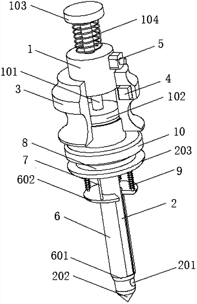
[0013] see figure 1 , the present invention provides a technical solution: a treatment tube device for oncology radiotherapy and chemotherapy, including a negative pressure cylinder 1, and the negative pressure cylinder 1 is provided with a movable rod 101 passing through a through hole on the upper side of the negative pressure cylinder 1, and the movable rod The lower end of 101 is fixed with a piston 102, the upper end of the movable rod 101 is fixed with a...


PUM


Abstract

The invention discloses a therapy tube device for oncology department chemoradiotherapy. The therapy tube device for oncology department chemoradiotherapy comprises a negative pressure cylinder, a needle tube is fixed to a bottom connecting opening of the negative pressure cylinder, a fixed sleeve is fixed to the outer side surface of the negative pressure cylinder, and an accumulator is installed in a cavity of the fixed sleeve; and a control switch is installed on the position, at the upper side of the fixed sleeve, of the side surface of the negative pressure cylinder, and the input end of the control switch is connected with the output end of the accumulator. According to the therapy tube device for oncology department chemoradiotherapy, partial tissue is sucked into a sucking hole of the needle tube through the negative pressure cylinder, and then a knife blade on a slide shell is utilized to conduct cutting; when tumor biopsy sampling is conducted on a patient, a sample can be prevented from being damaged, other living tissue surrounding a tumor can be protected in the sampling process, damage to other living tissue in a human body in the sampling process is avoided effectively, and the situation that serious sequelae are left to the patient can be avoided; and the structure is compact, operation can be achieved with one hand, using is convenient, and the therapy tube device is suitable for sampling pathological tissue when intracavitary tumor radiotherapy is conducted.

Description

technical field [0001] The invention relates to the technical field of treatment tubes for oncology radiotherapy and chemotherapy, in particular to a treatment tube device for oncology radiotherapy and chemotherapy. Background technique [0002] According to the existing technology, conservative treatment methods are often used for intracavitary tumors, and the combination of radiotherapy and chemotherapy is often used for specific operations. In some cases where surgical treatment is necessary, surgical treatment is often taken out of necessity However, due to the special location and environment of this tumor, even in the case of incision, it is difficult to achieve satisfactory results, but in actual operation, especially when using this treatment tube to perform surgery In the past, the tumor should be accurately characterized. According to the existing technology, it is necessary to slice and analyze the tumor. In clinical practice, when taking tumor biopsy samples from...

Claims


Application Information

Patent Timeline
Patent Type & Authority Applications(China)
IPC IPC(8): A61B10/02
Inventor 张颖邵玲玲
Owner 张颖
Learn More