Wire feeder and laser cladding device

A technology of wire feeder and wire feeding structure, which is applied in laser welding equipment, welding equipment, metal processing equipment, etc., can solve the problems of unfavorable cladding on the surface of the object to be clad, poor alignment effect, etc., and achieve the corrective effect Uniform and smooth, the effect is obvious, and the effect of ensuring the transmission quality

Active Publication Date: 2017-12-01
SUZHOU UNIV
View PDF7 Cites 7 Cited by
  • Summary
  • Abstract
  • Description
  • Claims
  • Application Information

AI Technical Summary

Problems solved by technology

[0005] The above laser cladding devices have the following problems: the wire feeding structure is to directly transport the wire to the surface of the object to be clad through the pinch roller, and the wire needs to be transported. During the transmission process, if the wire is bent, Increase the difficulty of passing, which is not conducive to the uniform cladding of the surface of the object to be clad; wherein, Chinese Patent Publication No. CN2608209Y discloses a wire feeder for laser cladding, including a frame (1), pinch wheels (2 ), motor (3), reducer (4), wherein the motor (3), reducer (4) are fixed on the frame (1), the output shaft of the motor (3) and the input shaft of the reducer (4) connection, the driving wheel of the pinch wheel pair (2) is fixed on the output shaft of the reducer (4), the driven wheel is installed on the side of the driving wheel, and the metal wire for laser cladding is clamped between the driving wheel and the driven wheel Sending down and feeding, the driven wheel of the pinch wheel pair (2) is installed on the frame (1) of the spring pressure regulating slide mechanism that can adjust the distance between the driven wheel and the driving wheel and ensure a certain pressure feeding force There is also a straightening mechanism at the tail of the pinch wheel pair (2) and at the front position that is consistent with the wire feed direction. The straightening mechanism includes several straightening rollers (5) that are arranged in two rows and staggered. In this case Disclosed is a wire feeder structure for a laser cladding device, which is provided with a straightening structure, and the straightening structure is provided with four straightening rollers arranged in a staggered manner, two of which are fixed rollers and two are adjustable rollers The roller is set on the adjustable sliding seat. The above-mentioned structure can preliminarily complete the straightening and conveying functions of the wire material, but the straightening effect is not good. At the same time, the adjustable roller is set on the adjustable sliding seat, which is inconvenient to adjust. Realize fine quantity control, and its wire feeding structure cannot realize wire feeding processing of different specifications of wire

Method used


Image

  • Wire feeder and laser cladding device
  • Wire feeder and laser cladding device
  • Wire feeder and laser cladding device

Examples


Embodiment Construction

[0040] The specific implementation manners of the present invention will be further described in detail below in conjunction with the accompanying drawings and embodiments. The following examples are used to illustrate the present invention, but are not intended to limit the scope of the present invention.

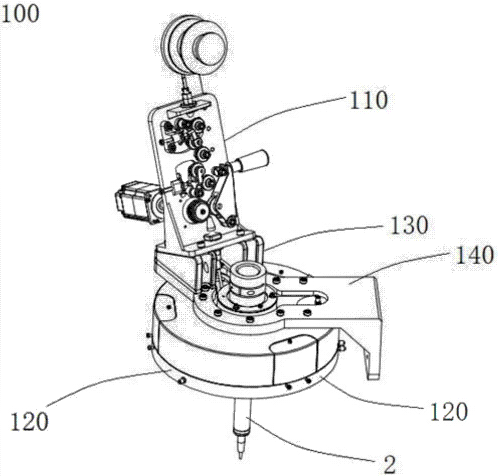
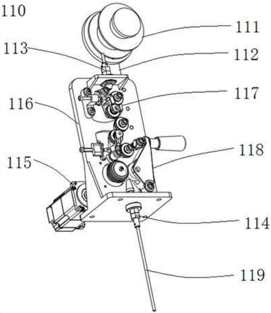
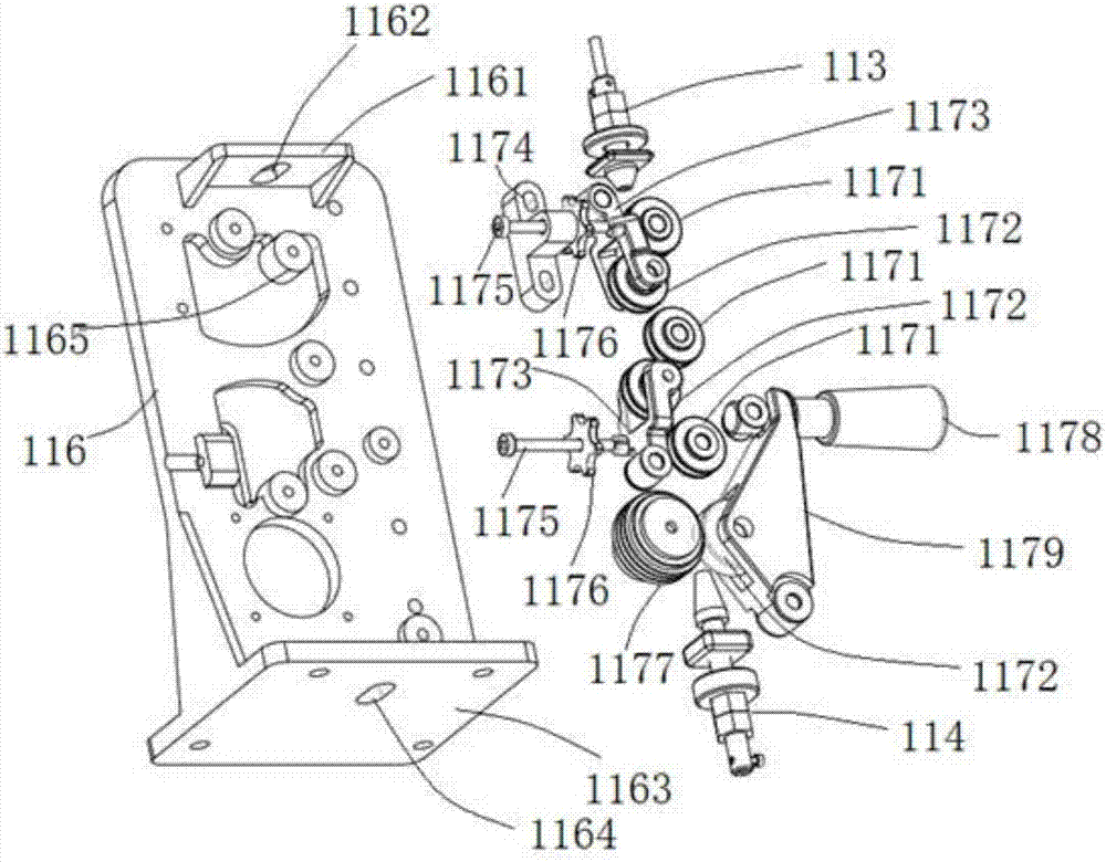
[0041] Seefigure 1 , Figure 4 , Figure 5 and Figure 6 , the laser cladding device of the present invention includes a wire feeder 110 and a nozzle 2, the wire feeder 110 and the nozzle are integrally arranged through a connecting bracket 140, the nozzle 2 is arranged under the connecting bracket, and the wire feeder 110 is arranged on Above the connection bracket 140, the connection bracket 140 connects the wire feeder 110 and the nozzle 2, the connection bracket 140 includes a body 143, a first extension 141 and a second extension 142, the first extension 141 is along the body 143 The second extension 142 extends along the vertical direction of the plane where the m...


PUM


Abstract

The invention provides a wire feeder and a laser cladding device. The wire feeder comprises a bearing part, a straightening structure and a wire feeding structure, and further comprises a wire disc bracket and a wire disc arranged on the wire disc bracket, wherein the straightening structure and the wire feeding structure are arranged on the bearing part; the wire feeding structure comprises a drive structure, a drive wheel and a regulating structure; the drive structure is arranged on the bearing part and is connected with the drive wheel; the regulating structure is matched with the drive wheel to press a wire. The invention also provides a laser cladding device using the wire feeder. The wire feeder further comprises an adjustable wire guide nozzle structure arranged on the bearing part, and a slide wheel structure with a V-shaped slot; and the wire guide slot of the active wheel can be regulated to realize transmission of wires of different specifications, so that wire transmission stability is guaranteed, and high-precision cladding shape and dimension precision are guaranteed.

Description

technical field [0001] The invention relates to a wire feeder, in particular to a wire feeder with a relatively straight structure capable of delivering wires of different specifications and a laser cladding device, belonging to the field of laser processing. Background technique [0002] Laser cladding is a laser surface modification technology, which is to add cladding materials (powder feeding, wire feeding, preset, etc.) The thin layer of metal quickly reaches a molten state. At this time, relying on the heat conduction of the workpiece itself, it is rapidly solidified and crystallized into a cladding layer, so as to obtain a modified layer or repair layer with metallurgical bonding with the base material, low dilution rate, and various characteristics. Compared with traditional surface treatment technologies such as surfacing, thermal spraying, and electroplating, it has many advantages, such as a wide range of applicable material systems, controllable dilution rate of ...

Claims


Application Information

Patent Timeline
Patent Type & Authority Applications(China)
IPC IPC(8): B23K26/352B23K26/70
CPCB23K26/352B23K26/702Y02P10/25
Inventor 傅戈雁吉绍山刘凡石拓石世宏鲁健
Owner SUZHOU UNIV
Why Eureka
Try Eureka