Supercharge Your Innovation With Domain-Expert AI Agents!

Positioning system for layered storage rack for automobile punching parts

A technology of automobile stamping parts and positioning system, which is applied in tool storage devices, manufacturing tools, etc., can solve the problems of large area, small thickness of large stamping parts, and difficult positioning, and achieve the effect of accurate positioning and convenient movement.

Inactive Publication Date: 2017-12-01
管远轮
View PDF1 Cites 0 Cited by
  • Summary
  • Abstract
  • Description
  • Claims
  • Application Information

AI Technical Summary

Problems solved by technology

[0002] There are many stamping parts in the automobile manufacturing industry, especially large stamping parts such as the roof of a car or the roof of a large vehicle. These large stamping parts are small in thickness and large in area, making it difficult to stack or transport them. Difficult, in order to improve the efficiency of handling, the manipulator stacks multiple large stamping parts on layered shelves, and the shelves are transported as a whole, which improves the transportation efficiency; the operation of the manipulator is controlled by the computer system, and the large stamping parts are self-positioned by the manipulator alone It cannot be realized, the operation of the manipulator must be precisely positioned, otherwise, it will lead to accidents; the accurate positioning of the layered shelves can ensure the operation of the manipulator, but the positioning of large-scale layered shelves is very difficult, and small deviations will cause the manipulator inoperable

Method used


Image

  • Positioning system for layered storage rack for automobile punching parts

Examples


Embodiment Construction

[0018] In the following, with reference to the drawings, through the description of the embodiments, the shape, structure, connection relationship and working principle of each part involved in the specific implementation of the present invention will be further described in detail.

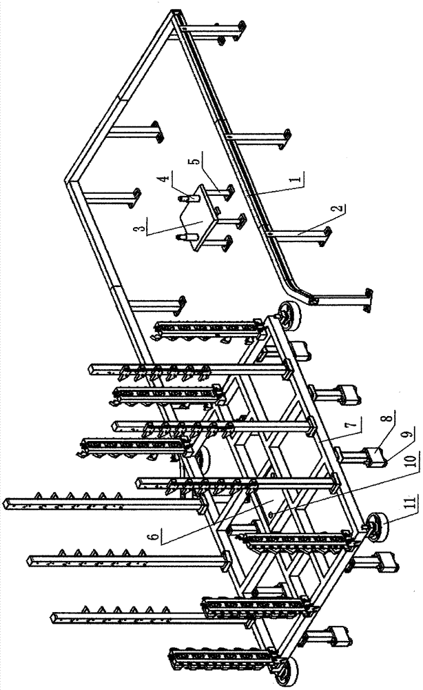
[0019] figure 1 It is a structural schematic diagram of a layered shelf positioning system for automobile stamping parts of the present invention; figure 1 A layered shelf positioning system for automotive stamping parts of the present invention is shown, including a layered shelf positioning assembly for automotive stamping parts and a flexible positioning part; the layered shelf positioning assembly for automotive stamping parts includes a positioning support and a guide rail surrounding three sides , The positioning support includes a positioning support body 3 and a support fixing rod 5. The positioning support body 3 is a horizontally placed rectangular plate that fits the positioning plate 6 w...


PUM


Abstract

The invention discloses a positioning system for a layered storage rack for automobile punching parts. The positioning system comprises an automobile punching part layered storage rack positioning assembly and flexible positioning parts. The automobile punching part layered storage rack positioning assembly comprises a positioning support and a guide rail arranged around the three faces of the positioning support. The positioning support comprises a positioning support body and support fixing rods. The positioning support body is a rectangular plate, wherein the rectangular plate is horizontally arranged and is matched with a positioning plate, and the positioning plate is provided with positioning holes and arranged in the middle of the layered storage rack. Positioning pins penetrating the positioning holes in the positioning plate in the middle of the layered storage rack are arranged on the upper end face of the rectangular plate. One end of each support fixing rod is fixedly connected to the ground, and the other ends of the support fixing rods are fixedly connected with the positioning support body. The flexible positioning parts are flexible materials attached to the bottoms of stand feet at the lower end of the automobile punching part layered storage rack. By the adoption of the technical scheme, the normal operation of a manipulator for stacking the large punching parts is guaranteed due to the precise positioning of the whole system.

Description

Technical field [0001] The invention relates to a layered shelf positioning system for automobile stamping parts. Background technique [0002] There are many stamping parts in the automobile manufacturing industry, especially large stamping parts such as the roof of a car or the roof of a large vehicle. The thickness of these large stamping parts is small, the area is large, and it is difficult to stack or transport. Modern enterprises use robots to solve the above problems. Difficult, in order to improve the efficiency of handling, the robot puts multiple large stamping parts on the layered shelves, and the shelves are transported as a whole, which improves the transportation efficiency; the operation of the robot is controlled by the computer system, and the large stamping parts are self-positioned by the robot alone. It cannot be achieved. The manipulator operation must be accurately positioned, otherwise, an accident will occur; the accurate positioning of the layered shelf ...

Claims


Application Information

Patent Timeline
IPC IPC(8): B25H3/04
Inventor 管远轮
Owner 管远轮
Features
  • R&D
  • Intellectual Property
  • Life Sciences
  • Materials
  • Tech Scout
  • Unparalleled Data Quality
  • Higher Quality Content
  • 60% Fewer Hallucinations
Learn More