AI technical title is built by Patsnap AI team. It summarizes the technical point description of the patent document.
A technology of locks and lock casings, applied in the field of locks, which can solve problems such as poor security, waste of effective travel of marbles, and reduction of lock key density, so as to achieve the effect of increasing density, preventing technical unlocking, and preventing violent opening
Inactive Publication Date: 2019-08-13
李运福
View PDF4 Cites 0 Cited by
Summary
Abstract
Description
Claims
Application Information
AI Technical Summary
This helps you quickly interpret patents by identifying the three key elements:
Problems solved by technology
Method used
Benefits of technology
Problems solved by technology
At the same time, this structure wastes the effective travel of the marbles, which reduces the key density of the lock and is easy to be opened by a locksmith, resulting in poor security.
Method used
Image
Click on the blue label to locate the original text in one second.
Reading with bidirectional positioning of images and text.
Examples
Embodiment 1
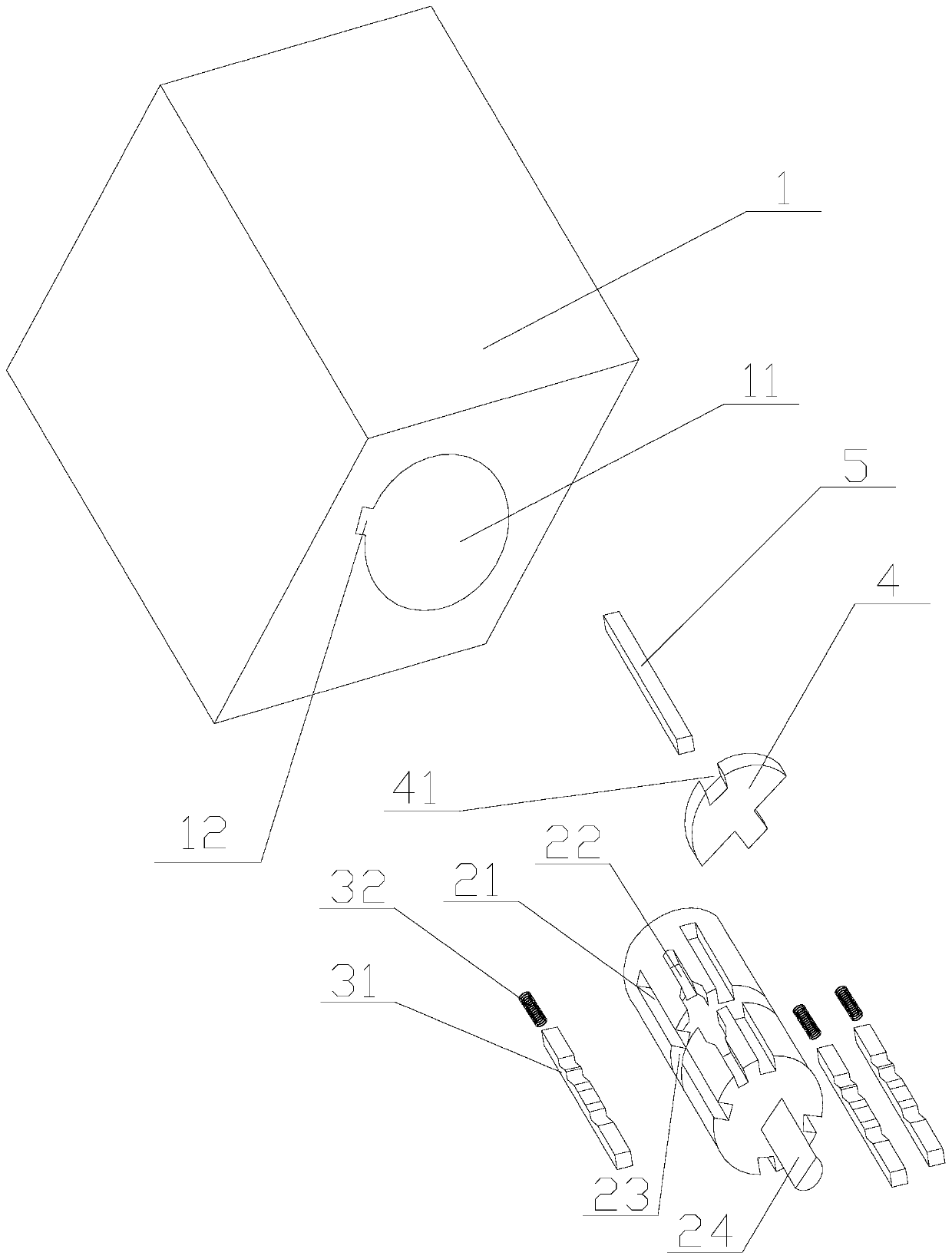
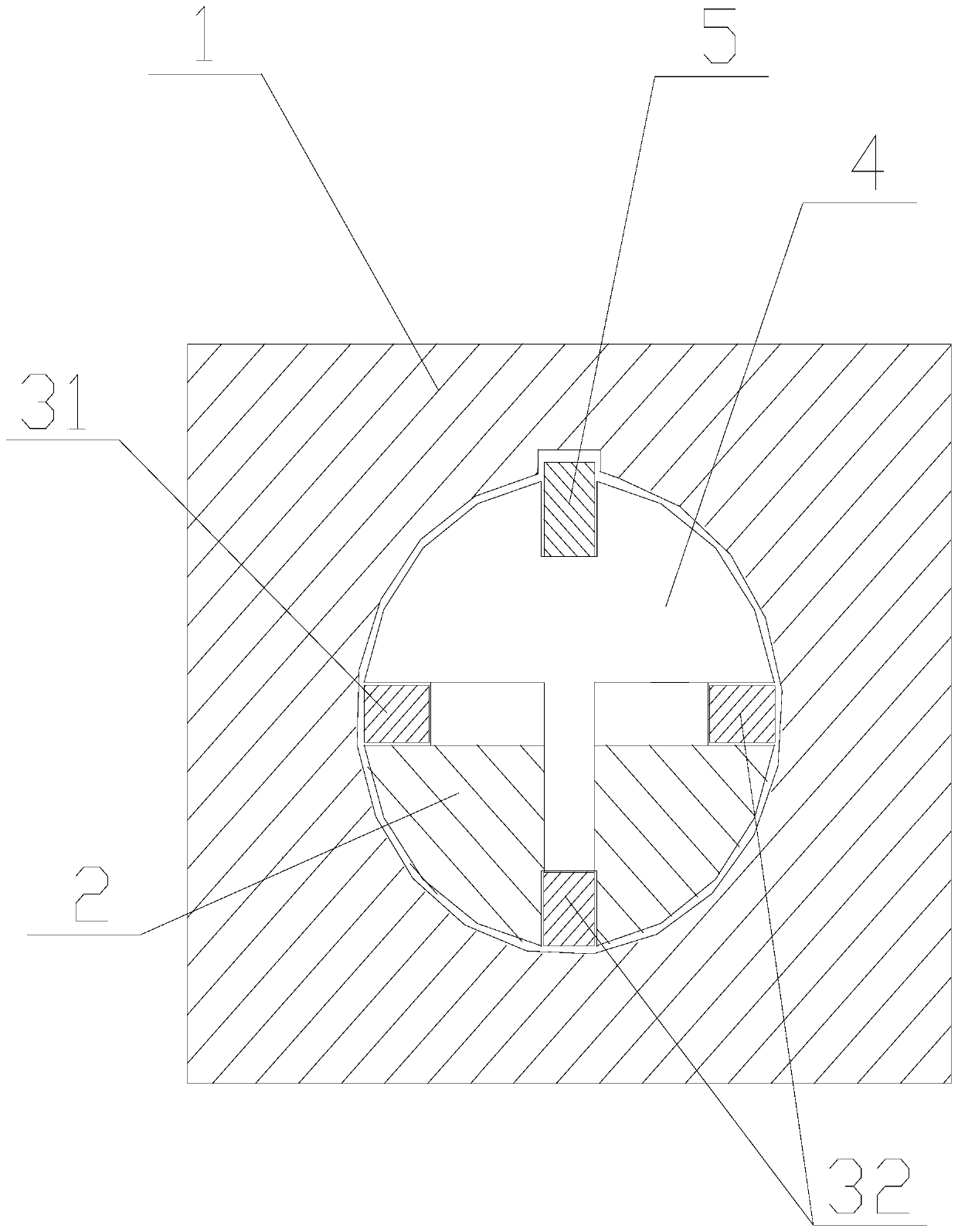
[0026] Figure 1 to Figure 3 An anti-theft lock according to an embodiment of the present invention is schematically shown. As shown in the figure, the device includes a lock case 1 and a lock cylinder 2 .
[0027] Wherein, a lock housing hole 11 and a lock housing groove 12 are provided inside the lock housing 1 .
[0028] The lock case groove 12 is arranged on the side wall of the lock case hole 11 .
[0029] The lock core 2 is arranged in the lock case hole 11 and can rotate freely in the lock case hole 11 .
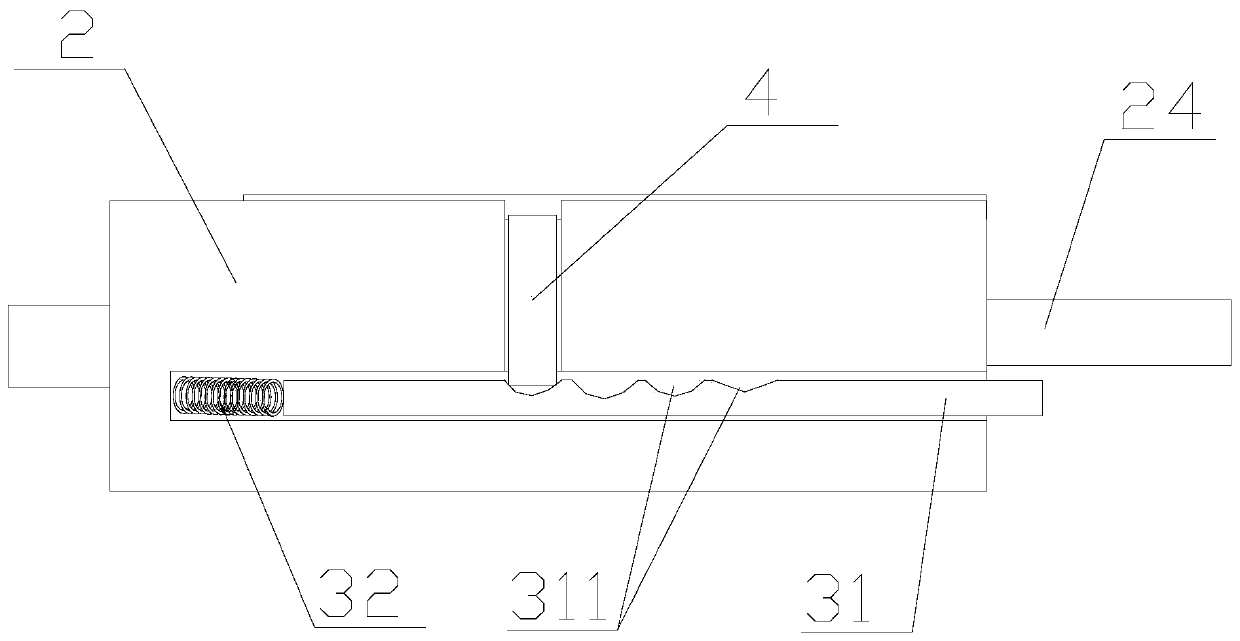
[0030] The side walls of the lock cylinder 2 are respectively provided with pin grooves 21 , lock bar grooves 22 and lock plate grooves 23 .
[0031] The lock cylinder 2 is generally provided with a plurality of pin grooves 21 .
[0032] For example, in this embodiment, the side wall of the lock cylinder 2 is provided with three pin grooves 21 .
[0033] A plurality of pin grooves 21 are respectively arranged axially along the lock cylinder 2 and the outer ends p...
Embodiment 2
[0058] Figure 4 and Figure 5 An anti-theft lock according to another embodiment of the present invention is schematically shown. As shown in the figure, the difference from Embodiment 1 is that a lock sleeve 6 is also included.
[0059] The lock sleeve 6 is provided with a lock sleeve hole 61 .
[0060] The lock sleeve 6 is arranged in the hole 11 of the lock case.
[0061] The lock core 2 is arranged in the lock sleeve hole 61 .
[0062] The side wall of the lock sleeve 6 is provided with a through lock pin hole 62 .
[0063] The locking pin 7 is disposed in the locking pin hole 62 .
[0064] When locking, the lock pin 7 enters the lock housing groove 12 to fix the position of the lock sleeve 6 and the lock housing 1, and the lock core 2 can rotate freely in the lock sleeve 6, thus forming a free-running lock.
[0065] In this embodiment, the thickness of the lock pin 7 is slightly greater than the depth of the lock pin hole 62. When locking, the inner end of the lock p...
PUM
Abstract
The invention discloses an anti-theft lock. The anti-theft lock comprises a lock shell and a lock cylinder. A lock shell hole and a lock shell groove are formed in the lock shell. The lock groove is formed in the side wall of the lock shell hole. The lock cylinder is arranged in the lock shell hole and can rotate freely in the lock shell hole. Marble grooves, a lock rod groove and a lock plate groove are formed in the side wall of the lock cylinder. The multiple marble grooves are formed in the lock cylinder. A marble assembly is arranged in each marble groove. Each marble assembly comprises a marble rod and a spring. A lock plate is arranged in the lock plate groove. The lock plate is in contact with the marble rods. Containing grooves are formed in each marble rod. A lock rod is arranged in the lock rod groove. The lock rod is in contact with the lock plate. The lock rod enters or protrudes out of the surface of the lock cylinder under the effect of the lock plate. By the adoption of the anti-theft lock, the key quantity is increased, the technical unlocking can be prevented effectively, and the safety performance is enhanced greatly; and besides, the marbles are designed in a rod shape, the strength is larger, the situation that the lock cylinder is twisted forcedly with a tool and the marble assemblies in the lock are catastrophically destroyed is avoided, and thus the forced unlocking is prevented effectively.
Description
technical field [0001] The invention relates to a lock, in particular to an anti-theft lock. Background technique [0002] Locks are common anti-theft tools. The tumbler lock is widely used because of its simple structure and practicality. The structure of the pin lock is roughly the same, that is, a group of cylindrical pins are installed in the pin hole of the lock cylinder, and the key has a corresponding depth of teeth. The method of unlocking is roughly the same, that is, the corresponding pins are moved up and down according to the height of the key teeth, so that the height of each lock cylinder pin is at the interface between the lock case and the lock core, and then the key is rotated to drive the lock core. , to achieve the purpose of unlocking. This type of lock can be inserted into various unlocking tools through the tooth channel for technical unlocking. Simultaneously, this kind of structure wastes the effective stroke of the marbles, makes the lockset key ...
Claims
Application Information
Patent Timeline
Application Date:The date an application was filed.
Publication Date:The date a patent or application was officially published.
First Publication Date:The earliest publication date of a patent with the same application number.
Issue Date:Publication date of the patent grant document.
PCT Entry Date:The Entry date of PCT National Phase.
Estimated Expiry Date:The statutory expiry date of a patent right according to the Patent Law, and it is the longest term of protection that the patent right can achieve without the termination of the patent right due to other reasons(Term extension factor has been taken into account ).
Invalid Date:Actual expiry date is based on effective date or publication date of legal transaction data of invalid patent.

