
Valve controlling system and method

A technology of valve control and valve opening, applied in the direction of valve details, valve devices, valve operation/release devices, etc., can solve the problems of difficult line laying, complicated setting process, poor safety, etc., and achieve perfect safety guarantee Mechanism, improved control accuracy, and the effect of a simple man-machine interface

Pending Publication Date: 2017-12-01
BEIJING UNIV OF TECH
View PDF6 Cites 9 Cited by
  • Summary
  • Abstract
  • Description
  • Claims
  • Application Information

AI Technical Summary

Problems solved by technology

The traditional valve control system uses multiple keys as input devices, which results in a complicated setting process, requires operators to have a good understanding of the operation process, and requires high professionalism. Some new valve control systems use FOUNDATION bus The fieldbus communicates with the control center to set the system parameters. When it is applied in some scenarios such as flow control of thermal pipelines, the laying of lines is difficult and costly.
[0004] The shortcomings of the traditional valve control system in function and use are increasingly exposed, such as poor safety, lack of perfect fault handling and alarm system, inability to realize man-machine dialogue well, and low control accuracy

Method used


Image

  • Valve controlling system and method
  • Valve controlling system and method
  • Valve controlling system and method

Examples


Embodiment Construction

[0030] In order to make the purpose, technical solutions and advantages of the embodiments of the present invention clearer, the technical solutions in the embodiments of the present invention will be clearly described below in conjunction with the accompanying drawings in the embodiments of the present invention. Obviously, the described embodiments are the Some, but not all, embodiments are invented. Based on the embodiments of the present invention, all other embodiments obtained by persons of ordinary skill in the art without making creative efforts belong to the protection scope of the present invention.

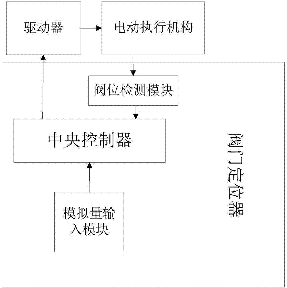
[0031] figure 1 It is a schematic structural diagram of a valve control system provided according to an embodiment of the present invention. like figure 1 As shown, the valve control system provided by the embodiment of the present invention includes: a valve positioner, a driver and an electric actuator; the valve positioner includes a central controller, an analog i...


PUM


Abstract

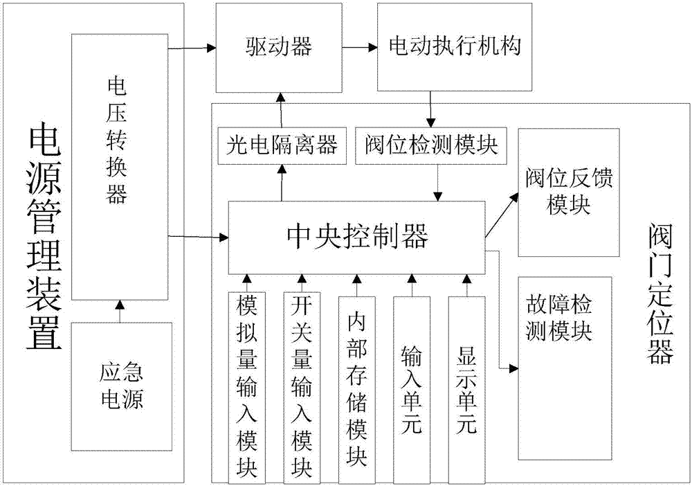
The invention provides a valve controlling system and method. The valve controlling system comprises a valve positioner, a driver and an electric actuating mechanism; the valve positioner comprises a central controller, an analog input module and a valve position detecting module, wherein the analog input module and the valve position detecting module are connected with the central controller. The valve controlling system further comprises a power management device, an optoelectronic isolator, a human-machine interface, an on-off input module, an internal storage module, a valve position feedback module and a breakdown detecting module. According to the valve controlling system and method, direct current voltage signals generated by transforming of the analog input module are received by the central controller and are compared with current valve opening signals, so that output signals are obtained; the electric actuating mechanism is controlled to adjust the valve opening signals by the driver according to the output signals; monitoring and self-diagnosis on system voltage, current, temperature and valve positions are conducted by the breakdown detecting module in real time; and the controlling precision of the system is improved, better security guaranty mechanism is provided, and reliability of the system is improved.

Description

technical field [0001] The present invention relates to the technical field of valve control, and more specifically, to a valve control system and a control method thereof. Background technique [0002] The intelligent valve control system is one of the important components of the electric control valve, which is widely used in electric power, metallurgy, petrochemical, pharmaceutical and other industries. With the improvement of the demand for production technology, the current industrial production site needs the valve control system to develop in the direction of intelligence. It needs to have perfect self-diagnosis function, safe emergency response mechanism, and higher control precision performance. Traditional valves often cannot meet the current requirements. Market demand. [0003] Traditional valve control systems usually use single-turn or multi-turn potentiometers to detect valve opening signals, but the detection results are affected by power fluctuations and th...

Claims


Application Information

Patent Timeline
Patent Type & Authority Applications(China)
IPC IPC(8): F16K31/04F16K37/00
CPCF16K31/046F16K37/0041
Inventor 左国玉邱永康卢佳豪
Owner BEIJING UNIV OF TECH
Learn More