Wide-field-of-view and large-depth-of-field variable-resolution non-scanning streak tube laser imaging system

A technology of laser imaging and stripe tube, which is applied in radio wave measurement system, re-radiation of electromagnetic waves, utilization of re-radiation, etc., can solve problems such as reduction of laser echo energy, reduction of imaging depth of field, reduction of imaging depth of field, etc., to achieve a solution Effect of high spatial resolution and increased longitudinal range

Inactive Publication Date: 2017-12-01
BEIJING INSTITUTE OF TECHNOLOGYGY
View PDF5 Cites 12 Cited by
  • Summary
  • Abstract
  • Description
  • Claims
  • Application Information

AI Technical Summary

Problems solved by technology

For non-scanning streak tube laser imaging radar, in order to pursue high spatial resolution, optical fibers with smaller diameters need to be used in the image plane of the receiving optical system, and the reduction of the diameter of the optical fibers will result in the laser echo energy received by each optical fiber The reduction of the laser echo energy will reduce the detection distance of the laser radar system
In order to pursue a large field of view, more optical fibers need to be included in the optical fiber conversion system, and the increase in the number of optical fibers will inevitably reduce the vertical range corresponding to each optical fiber on the fluorescent screen of the stripe tube. When the time resolution is constant, the reduction in the vertical range is equivalent to Due to the reduction of the imaging depth of each pixel; therefore, limited by the inherent imaging principle, the general non-scanning stripe tube laser imaging radar cannot solve the contradiction between high spatial resolution, long-distance detection, large field of view and large depth of field
Especially in terms of depth of field (for range images, imaging depth of field refers to the distance detection range of pixels, which can also be called range gate gating distance. Stripe tube lidar needs trigger signal delay equipment and range gating method In order to achieve long-distance detection), compared with other laser imaging radar systems, the striped tube laser imaging radar is at a disadvantage, and the non-scanning mechanism further reduces its imaging depth of field

Method used


Image

  • Wide-field-of-view and large-depth-of-field variable-resolution non-scanning streak tube laser imaging system
  • Wide-field-of-view and large-depth-of-field variable-resolution non-scanning streak tube laser imaging system

Examples


Embodiment

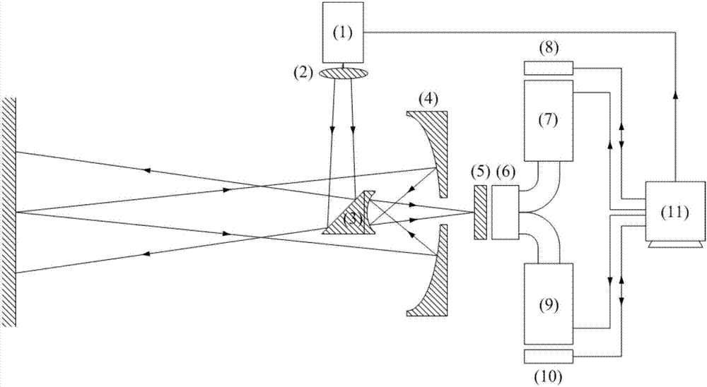
[0024] A non-scanning stripe tube laser imaging system with variable resolution and large field of view and large depth of field. Such as figure 1 As shown, the device includes a pulsed laser 1, a beam expander shaping optical system 2, a plane mirror 3, a receiving optical system 4, a microlens array 5, an optical fiber image transmission bundle 6, a streak tube 1 7, a CCD camera 1 8, a streak tube II 9, CCD camera II 10, control and processing system 11;

[0025] The pulse laser 1 can emit a laser pulse beam with a wavelength of 1064nm, a pulse width of 5ns, a repetition rate of 50Hz and a small divergence angle after receiving the pulse trigger signal. The laser needs to have good monochromaticity and strong stability. and good heat dissipation characteristics;

[0026] The beam expansion and shaping optical system 2 has multiple lenses, and the surface of the lens is coated with an anti-reflection coating in the 1064nm band. The emission optical system has two functions ...


PUM


Abstract

The invention relates to a wide-field-of-view and large-depth-of-field variable-resolution non-scanning streak tube laser imaging system, and belongs to the technical field of photoelectric imaging. The system mainly comprises a pulse laser, transmitting and receiving optical systems, a reflecting mirror, a micro-lens array, an optical fiber image bundle, streak tubes I / II, CCD cameras I / II and a control and processing system. The basic principle is that the pulse laser emits laser pulses, the laser irradiates to a target object through the transmitting optical system and the reflecting mirror, and the reflected laser is received by the receiving optical system and forms an image on the micro-lens array. The image plane is non-uniformly sampled by the micro-lens array and the optical fiber image bundle and then coupled to the photoelectric cathodes of the two streak tubes, the two CCD cameras acquire the streak image on two fluorescent screens and transmit the streak image to the control and processing system, and finally the intensity image and the distance image of the target can be obtained through the algorithm. The contradiction among the high spatial resolution, long distance detection, wide field of view and large depth of field of the non-scanning streak tube laser imaging radar can be solved.

Description

technical field [0001] The invention relates to a non-scanning stripe tube laser imaging system with variable resolution and large field of view and large depth of field, belonging to the technical field of photoelectric imaging. Background technique [0002] Stripe tube laser imaging radar is a new system of laser imaging radar that appeared at the end of the last century. It can be divided into scanning and non-scanning imaging mechanisms. Compared with the traditional point-scanning lidar, it has technical advantages such as high precision and high frame rate, and is an effective means to quickly obtain target intensity and distance information. After more than ten years of research, the stripe tube laser imaging radar has developed a variety of imaging methods such as single slit, multi-slit, and polarization. Foreign research institutions have successfully developed a variety of striped tube lidar systems, and successfully applied them to mine reconnaissance, fish scho...

Claims


Application Information

Patent Timeline
Patent Type & Authority Applications(China)
IPC IPC(8): G01S17/89G01S7/481
CPCG01S7/481G01S7/4818G01S17/89
Inventor 韩绍坤夏文泽翟宇曹京亚
Owner BEIJING INSTITUTE OF TECHNOLOGYGY
Why Eureka
Try Eureka