
Monitoring lens

A lens and lens technology, applied in the field of camera lenses, can solve the problems of low resolution quality, small viewing angle, poor resolution quality, etc., and achieve the effects of small focus drift, reduced number of lenses, and long service life

Active Publication Date: 2017-12-01
JIANGXI LIANCHUANG ELECTRONICS CO LTD
View PDF19 Cites 11 Cited by
  • Summary
  • Abstract
  • Description
  • Claims
  • Application Information

AI Technical Summary

Problems solved by technology

[0004] Existing surveillance cameras generally have defects such as overall length, small viewing angle, large temperature influence, low resolution quality, small target surface, and high cost.
As the day and night confocal lens of patent document CN105301739A uses three plastic material aspheric lenses and 2 glass lenses, its field of view angle is too small and the total length is too long; as the large target surface day and night confocal monitoring lens of patent document CN105388591A is used The number of lenses is as many as 12, which increases the cost, and the field of view angle is too small, and the resolution quality is poor; such as the patent document CN102323657A security day and night dual-use lens, although the lens resolution is improved and the total length is reduced by using multiple aspheric plastic material lenses , but the field of view angle of the lens is not large enough, and the target surface is too small

Method used


Image

  • Monitoring lens
  • Monitoring lens
  • Monitoring lens

Examples


Embodiment 1

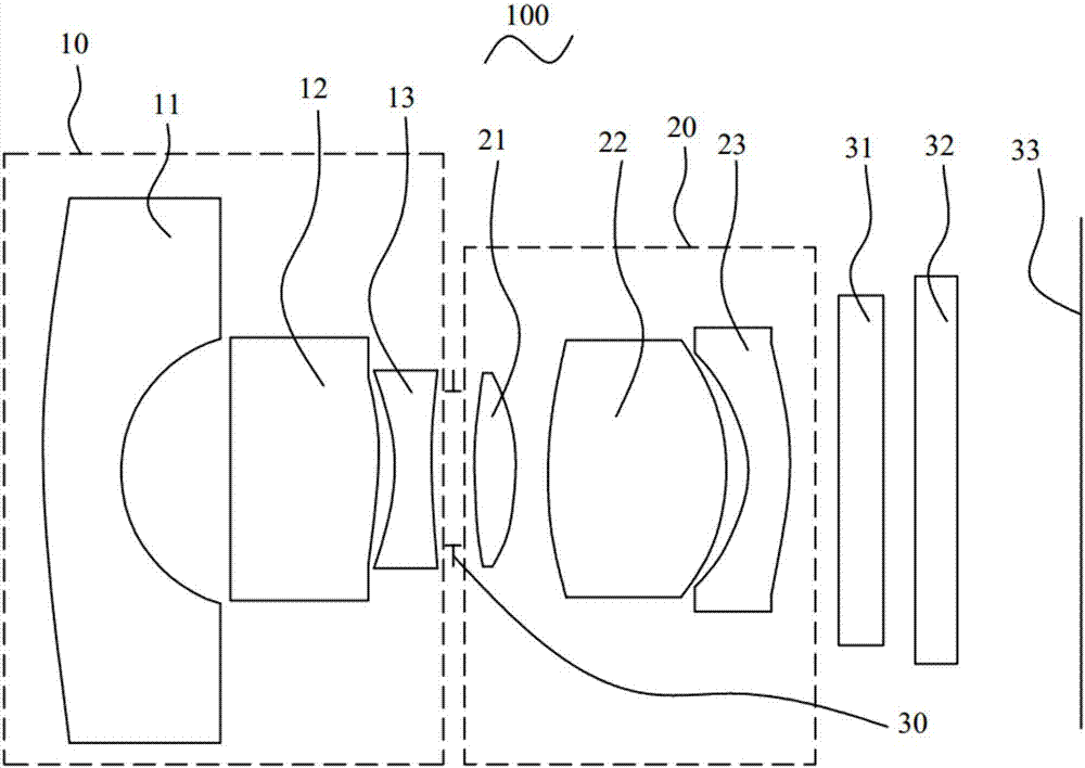
[0061] see figure 1 , is a schematic cross-sectional structure diagram of the surveillance lens 100 provided in the first embodiment of the present invention, wherein the relevant parameters of each lens in the surveillance lens 100 provided in this embodiment can be found in Table 1.

[0062] Table 1

[0063]

[0064]

[0065] The aspherical parameters of the third lens 13 , the fourth lens 21 , and the sixth lens 23 in this embodiment are shown in Table 2.

[0066] Table 2

[0067] Surface serial number

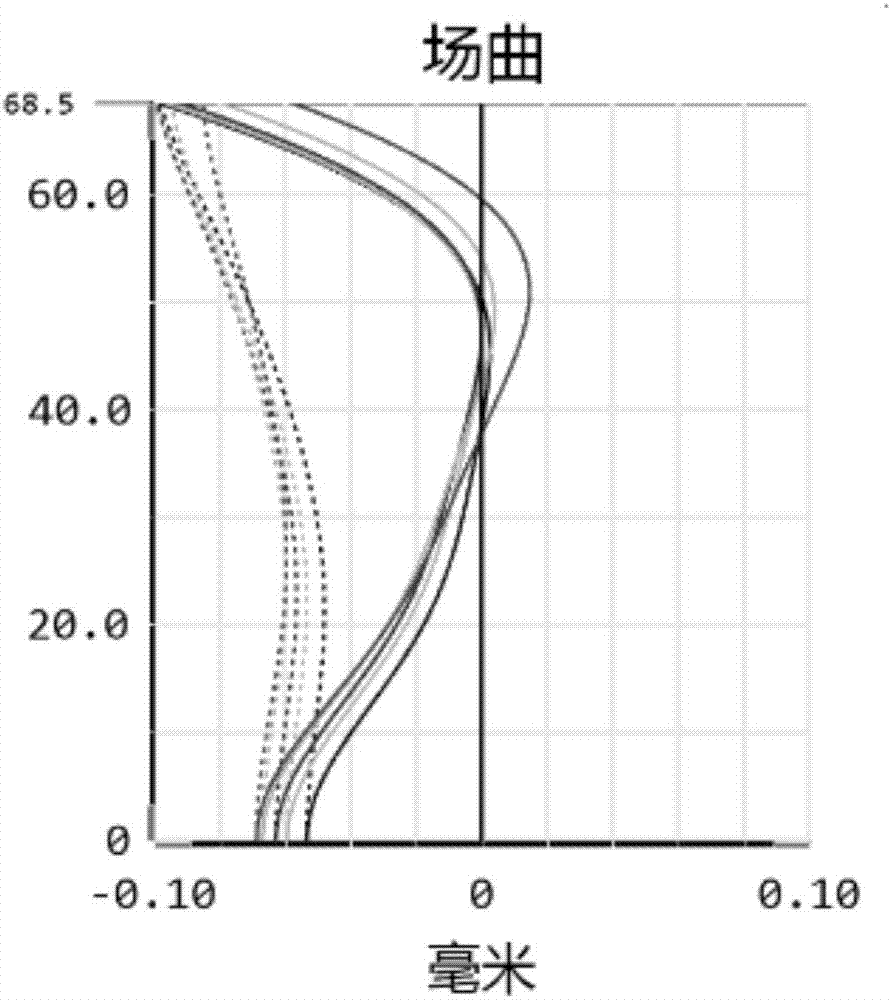
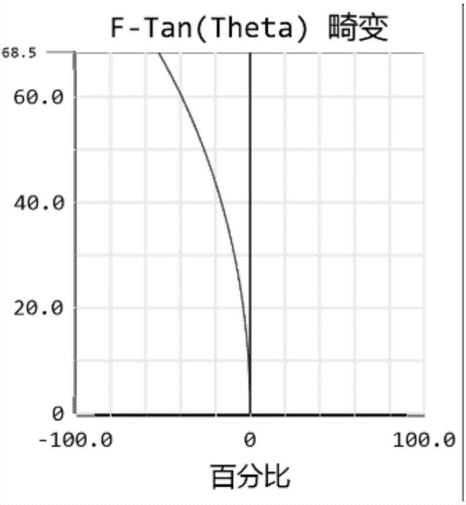
[0068] see figure 2 and image 3 , are respectively the field curvature and distortion curves of the monitoring lens 100 in Embodiment 1, and the on-axis penalty spherical aberration chromatic aberration curve at the end of the field of view is as follows Figure 4 shown by Figure 2 to Figure 4 It can be seen that field curvature, distortion and on-axis penalty spherical aberration chromatic aberration are well corrected. Its MTF curve is Figure 5 ...

Embodiment 2

[0070] The monitoring lens 100 provided in this embodiment is substantially the same as that in the first embodiment, except that the relevant parameters of each lens of the monitoring lens in this embodiment are different from those in the first embodiment. Please refer to Table 3 for relevant parameters of each lens of the surveillance lens 100 in this embodiment.

[0071] table 3

[0072]

[0073]

[0074] The aspherical parameters of the third lens 13 , the fourth lens 21 , and the sixth lens 23 in this embodiment are shown in Table 4.

[0075] Table 4

[0076] Surface serial number

[0077] see Figure 8 and Figure 9 , for the field curvature and distortion curve of the monitoring lens 100 provided in Embodiment 2, the on-axis point spherical aberration chromatic aberration curve at the end of the field of view is as follows Figure 10 As shown, its MTF curve is shown as Figure 11 shown, according to Figure 8 to Figure 11 It can be seen that the f...

Embodiment 3

[0079] The monitoring lens 100 provided in this embodiment is substantially the same as that in the first embodiment, except that the relevant parameters of each lens of the monitoring lens 100 in this embodiment are different from those in the first embodiment. Please refer to Table 5 for relevant parameters of each lens of the surveillance lens 100 in this embodiment.

[0080] table 5

[0081]

[0082] The aspherical parameters of the third lens 13 , the fourth lens 21 , and the sixth lens 23 in this embodiment are shown in Table 6.

[0083] Table 6

[0084] Surface serial number

K

B

C

D

E

5

3.66E+00

-1.00E-02

1.95E-02

-6.52E-03

1.26E-03

6

-1.61E+02

-2.72E-02

2.81E-02

-1.04E-02

2.09E-03

8

-2.92E+01

1.99E-04

-1.07E-03

2.90E-04

-6.54E-05

9

-1.43E+01

-3.82E-02

8.36E-03

-2.37E-03

9.91E-05

12

-3.20E+00

-2.88E-02

6.05E-03

-9.67E-04

6.15E-05

13...


PUM


Abstract

The invention provides a monitoring lens, which comprises a first lens group, a second lens group and a diaphragm, and is characterized in that the first lens group sequentially comprises a first lens with negative focal power, a second lens with positive focal power and a third lens with negative focal power from an object side to an imaging plane; the second lens group comprises a fourth lens with positive focal power, a fifth lens with positive focal power and a sixth lens with negative focal power from the object side to the imaging plane; the first lens, the second lens and the fifth lens adopt a glass spherical lens, the third lens, the fourth lens and the sixth lens adopt a plastic aspherical lens, and the optical centers of the lenses are located on the same straight line. According to the invention, three plastic aspherical lenses are adopted, so that the number of lenses is reduced, and the length, the weight and the manufacturing cost of the lenses are reduced; and the aberration of the lens is enabled to be effectively corrected through matching and combining the lenses of different materials, the reasonable focal power and the air gap distribution, and the monitoring lens has the advantages that small focus shift is generated at high and low temperatures and the like.

Description

technical field [0001] The invention relates to the field of camera lens technology, in particular to a monitoring lens. Background technique [0002] With the rapid development of science and technology, people have a higher level of understanding of security, and surveillance cameras were born immediately. In recent years, surveillance cameras have become a major force in the security industry, driving the continuous advancement and rapid development of the security industry. , People pay more and more attention to performance issues such as the quality of its imaging effect and the size of the field of view. [0003] The existing monitoring lens includes a first lens group, a diaphragm and a second lens group in sequence from the object side to the imaging surface along the optical axis, and through the optical combination of different lenses in the first lens group, diaphragm and second lens group, In order to achieve different imaging display effects. [0004] Existi...

Claims


Application Information

Patent Timeline
Patent Type & Authority Applications(China)
IPC IPC(8): G02B13/00G02B13/06
CPCG02B13/0045G02B13/06
Inventor 李伟娜高博韩建邓厚壮
Owner JIANGXI LIANCHUANG ELECTRONICS CO LTD
Learn More