Impact type piling machine motor

An electromechanical and impact-type technology, applied in the direction of electromechanical devices, electrical components, electric components, etc., can solve the problems of generating a large amount of exhaust gas, achieve the effects of increasing power density, avoiding car out-of-control phenomena, and improving heat dissipation efficiency

Inactive Publication Date: 2017-12-01
刘志运
View PDF0 Cites 1 Cited by
  • Summary
  • Abstract
  • Description
  • Claims
  • Application Information

AI Technical Summary

Problems solved by technology

At the same time, as we all know, most construction machinery now uses fuel to drive the engine, which will produce a lot of exhaust gas during use, thus promoting the generation of impact pile drivers.

Method used


Image

  • Impact type piling machine motor

Examples


Embodiment 1

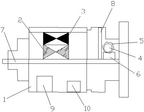
[0018] An impact pile driver motor, comprising a housing 1, a stator 2, a rotor 3, a fan 4, a windshield 5 and a battery 6, a rotating shaft 7 is arranged in the middle of the housing 1, and the stator 2 is arranged at the center of the rotor 3 Outside, one end inside the housing 1 is provided with a partition 8, one side of the partition 8 is provided with the fan 4, and the other side of the partition 8 is provided with the stator 2 and the rotor 3. The windshield 5 is arranged on the outside of the fan 4, the battery 6 is arranged below the fan 4, and the outer wall of the casing 1 is radially distributed with heat dissipation ribs, and the heat dissipation ribs are arranged radially Distributed at intervals, the heat dissipation ribs are covered with an outer cover plate, the outer cover plate is provided with heat dissipation grooves and heat dissipation holes, the heat dissipation grooves are provided with heat dissipation fins, and the heat dissipation fins and the heat ...

Embodiment 2

[0021] An impact pile driver motor, comprising a housing 1, a stator 2, a rotor 3, a fan 4, a windshield 5 and a battery 6, a rotating shaft 7 is arranged in the middle of the housing 1, and the stator 2 is arranged at the center of the rotor 3 Outside, one end inside the housing 1 is provided with a partition 8, one side of the partition 8 is provided with the fan 4, and the other side of the partition 8 is provided with the stator 2 and the rotor 3. The windshield 5 is arranged on the outside of the fan 4, the battery 6 is arranged below the fan 4, and the outer wall of the housing 1 is radially distributed with cooling ribs, and the outer wall of the cooling rib is covered with a cover The outer cover plate is provided with heat dissipation grooves and heat dissipation holes, the heat dissipation grooves are provided with heat dissipation fins, and the heat dissipation fins and the heat dissipation holes are arranged in a dislocation manner.

[0022] The inside of the housi...


PUM


Abstract

The invention relates to a motor for an impact pile driver, which includes a casing, a stator, a rotor, a fan, a wind cover and a storage battery. A rotating shaft is arranged in the middle of the casing, the stator is arranged outside the rotor, and A baffle is provided at one end of the baffle, the fan is provided on one side of the baffle, the stator and the rotor are provided on the other side of the baffle, and the windshield is provided outside the fan, The storage battery is arranged below the fan, and heat dissipation ribs are radially distributed on the outer wall of the housing. The heat dissipation ribs are covered with an outer cover plate, and the outer cover plate is provided with heat dissipation grooves and heat dissipation holes. The heat dissipation grooves A cooling fin is arranged in the middle, and the cooling fin and the cooling hole are arranged in a dislocation manner. The motor designed by the invention can effectively avoid the problem of circuit burnout caused by excessive temperature, thereby greatly improving the safety and stability of the impact pile driver.

Description

technical field [0001] The invention relates to the field of construction machinery power systems, in particular to an impact pile driver motor. Background technique [0002] With the rapid development of social economy, people have higher and higher requirements for the quality of life and living environment. At present, construction machinery has become an indispensable tool for large-scale project construction and urban rescue. The number of construction machinery and equipment is also increasing. At the same time, as we all know, most of the construction machinery now uses fuel to drive the engine, which will produce a large amount of exhaust gas during use, thus promoting the generation of impact pile drivers. [0003] As the main component of precision machinery, the motor of construction machinery has a crucial influence on the working accuracy of the actuator, so it has become a new industrial requirement to accurately detect the working state of the motor. The imp...

Claims


Application Information

Patent Timeline
Patent Type & Authority Applications(China)
IPC IPC(8): H02K11/00H02K9/04H02K5/20H02K5/18H02K9/19
CPCH02K11/0094H02K5/18H02K5/20H02K9/04H02K9/19
Inventor 刘志运
Owner 刘志运
Why Eureka
Try Eureka