Power module, converter and wind generating set
A technology for power modules and converters, which is applied to conversion devices and circuits that convert AC power input into DC power output and output power, can solve the problems affecting the current sharing effect, the difficulty of designing AC bus circuits, and paralleling power semiconductor devices. Inconsistent temperature, etc., to achieve the effect of confluence and current sharing
- Summary
- Abstract
- Description
- Claims
- Application Information
AI Technical Summary
Problems solved by technology
Method used
Image
Examples
Embodiment 1
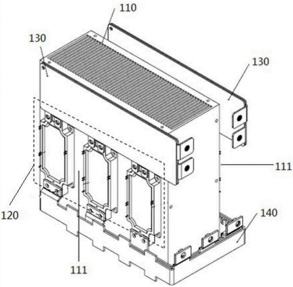
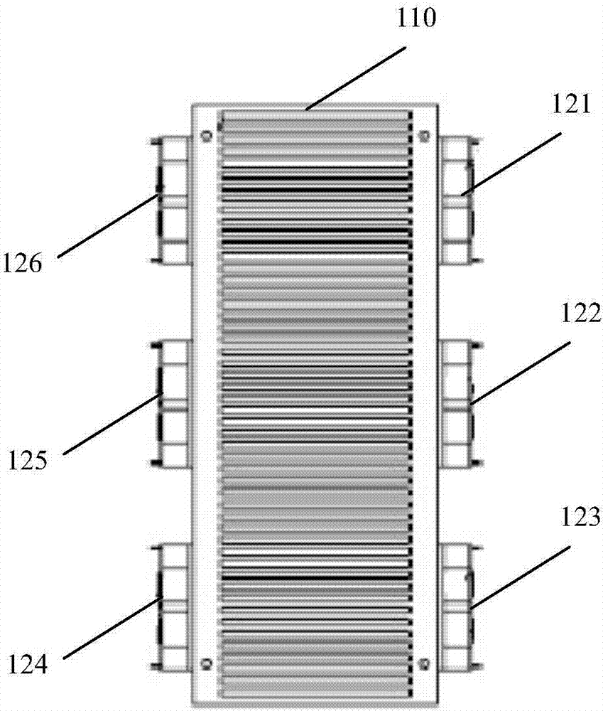
[0029] figure 1 Schematic diagram of the power module structure provided by the embodiment of the present invention Figure 1 ,Such as figure 1 As shown, the power module includes: a double-sided radiator 110, and two IGBT modules 120 with the same structure are symmetrically arranged on the front and rear heat dissipation substrates 111 of the double-sided radiator 110;
[0030] Two DC positive and negative laminated busbars 130 with the same structure are symmetrically arranged on the upper ends of the front and rear heat dissipation substrates 111 of the double-sided radiator 110, and each DC positive and negative laminated busbar 130 is connected to the same heat dissipation substrate 111. The DC input terminal of the IGBT module 120 is connected; the confluence position of the two DC positive and negative laminated busbars 130 is set on the side of the double-sided radiator 110;
[0031] The front and rear heat dissipation substrates 111 and the lower ends of the sides ...
Embodiment 2
[0044] Based on the power module described in the above embodiments, Figure 4 to Figure 7 The structure of the above-mentioned AC laminated busbar will be described in detail, where Figure 4 The schematic diagram of the structure of the AC laminated busbar provided by the embodiment of the present invention is to describe the structure of the AC laminated busbar 140 as a whole. Figure 5 , Figure 6 and Figure 7 are respectively for Figure 4 The structure of each AC busbar contained in .
[0045] First, if Figure 4 As shown, in order to ensure that the impedance parameters corresponding to the structure between the confluence position of each AC busbar in the AC laminated busbar 140 and the position used to connect the two AC output ends are equal, when designing the structure of the AC busbar, it may be There are two situations:
[0046] In the first type, the distance from the confluence position of the AC busbar to the position used to connect the two AC output t...
Embodiment 3
[0058] In this embodiment, the structure of the AC laminated busbar 140 will be described in detail according to the specific circuit structure constituting the IGBT module. As mentioned above, in the power module, the IGBT module 120 may be any one of a three-phase full-bridge circuit structure, an H-bridge circuit structure or a single-phase circuit structure including IGBT power devices.
[0059] Specifically, when the IGBT module 120 is a three-phase full-bridge circuit structure including IGBT power devices, the structure of the AC laminated busbar may specifically be a laminated busbar structure including three AC busbars, wherein:
[0060] The distance between the confluence position of one AC busbar in the AC laminated busbar and the position used to connect the two AC output terminals is the same, and the structure between the confluence position of the AC busbar and the position of the two AC output terminals is the same and symmetrical ;
[0061] The distances from...
PUM
 Abstract
Description
Claims
Application Information
 - R&D
- Intellectual Property
- Life Sciences
- Materials
- Tech Scout
- Unparalleled Data Quality
- Higher Quality Content
- 60% Fewer Hallucinations
Browse by: Latest US Patents, China's latest patents, Technical Efficacy Thesaurus, Application Domain, Technology Topic, Popular Technical Reports.
© 2025 PatSnap. All rights reserved.Legal|Privacy policy|Modern Slavery Act Transparency Statement|Sitemap|About US| Contact US: help@patsnap.com


