Elevator system

A technology of equipment and elevators, applied in elevators, transportation and packaging, etc., can solve the problems of not being able to know the damage of the bearing mechanism, achieve the effect of reducing the current intensity or voltage, and simplifying the monitoring system

Active Publication Date: 2017-12-01
INVENTIO AG
View PDF5 Cites 3 Cited by
  • Summary
  • Abstract
  • Description
  • Claims
  • Application Information

AI Technical Summary

Problems solved by technology

[0005] Although the monitoring method introduced in this prior art is reliable in monitoring the fracture of the tension carrier, it cannot know other damages of the load-carrying mechanism.

Method used


Image

  • Elevator system
  • Elevator system
  • Elevator system

Examples


Embodiment Construction

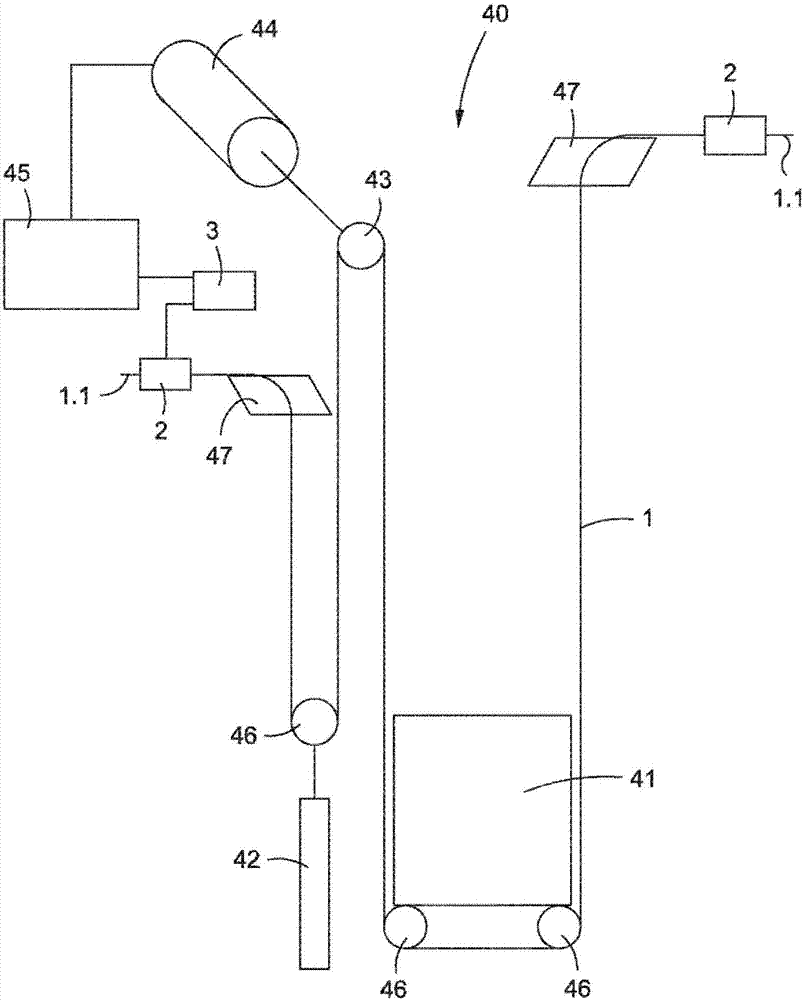
[0032] exist figure 1 The elevator installation 40 , shown in an exemplary and schematic manner, comprises an elevator car 41 , a counterweight 42 as well as a support mechanism 1 and a drive pulley 43 with an associated drive motor 44 . The drive pulley 43 drives the supporting mechanism 1 and thereby moves the elevator car 41 in the opposite direction to the counterweight 42 . The drive motor 44 is controlled by an elevator control 45 . The car 41 is designed to load and transport people or goods between floors of a building. The car 41 and the counterweight 42 are guided along guide means (not shown). In this example, the car 41 and the counterweight 42 are respectively suspended on carrying rollers 46 . In this case, the support means 1 is fixedly arranged on the first support means fastening device 47 and is then firstly guided around the support rollers 46 of the counterweight 42 . The carrier 1 is then placed on the drive pulley 43 in order to guide the carrier roll...


PUM


Abstract

The invention discloses an elevator system (40) which comprises a suspension means (1) that includes a plurality of tension members (5) in a common jacket (6). The tension members (5) of the suspension means (1) are electrically interconnected in an electric circuit which comprises a current or voltage source (12) and a measuring device (13). The measuring device (13) is positioned between a first group of tension members and a second group of tension members.

Description

technical field [0001] The invention relates to a device and a method for monitoring at least one support means in an elevator installation. Background technique [0002] In elevator installations, steel cables are conventionally used as support means for supporting and / or driving the elevator car. According to further developments of such steel cables, belt-shaped support means are also used, which have a tension carrier and a sheath arranged around the tension carrier. However, such a belt-shaped carrier cannot be monitored in a conventional manner, since the tension carrier, which determines the breaking load of the carrier, cannot be seen through the casing. [0003] In order to monitor such a tension carrier in a belt-like carrier, a test current can be applied to the tension carrier. In the circuit thus formed, the current or current intensity, voltage, resistance or conductivity are measured. With the aid of the measured values ​​in this way, it is possible to draw...

Claims


Application Information

Patent Timeline
Patent Type & Authority Applications(China)
IPC IPC(8): B66B7/12
CPCB66B7/1223B66B5/0018B66B7/062
Inventor 约尔斯·林德埃格
Owner INVENTIO AG
Why Eureka
Try Eureka