

Manufacturing method of inner pot
A manufacturing method and a technology for an inner pot are applied to the structure of cooking utensils, hollow objects, cooking utensils and other directions, and can solve the problems such as the cover body cannot be properly covered above the inner pot, the sealing effect of the inner pot is affected, and the deviation is avoided. Achieving good heat gathering effect, enhancing metallic and three-dimensional feeling, and increasing stability
- Summary
- Abstract
- Description
- Claims
- Application Information
AI Technical Summary
Problems solved by technology
Method used
Image

Examples
Embodiment approach 1
[0053] The inner pot manufactured according to the inner pot manufacturing method of the present invention can be used in various cooking utensils, such as an electric rice cooker, an electric pressure cooker or other cooking utensils heated by a heating device such as a heating plate or a heating coil. And, the inner pot manufactured according to the inner pot manufacturing method of this embodiment can be applied to a cooking utensil having a steaming layer.
[0054] The following first briefly describes the structures of the inner pot and the steaming layer in the cooking appliance.
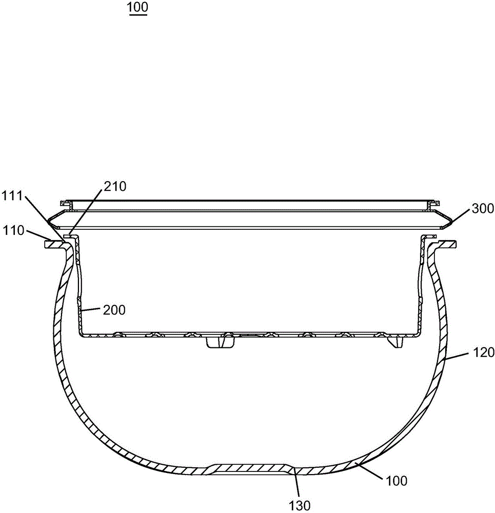
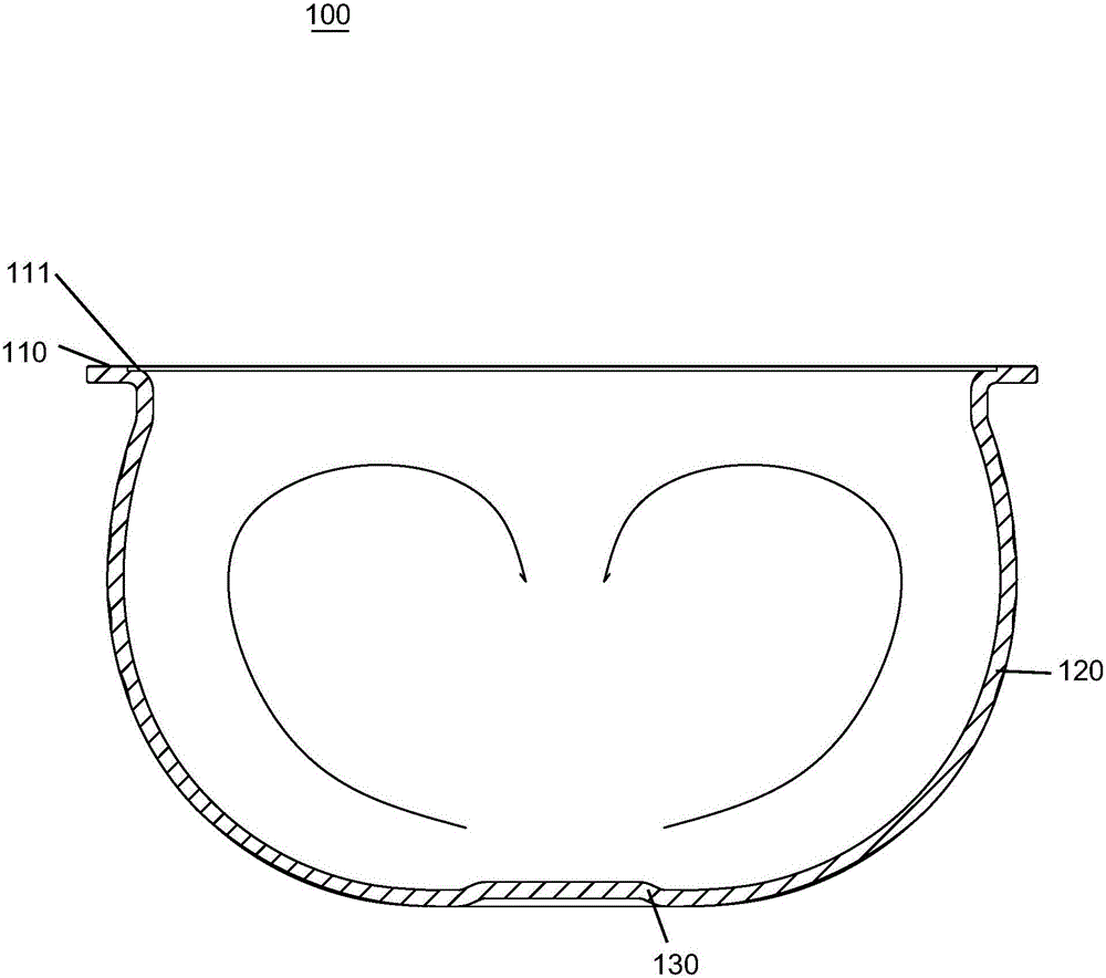
[0055] Such as figure 2 As shown, the inner pot 100 may be formed in the shape of a body of revolution, which includes a side wall 120 and a bottom wall 130 connected to the side wall 120 . The upper surface of the inner pot has a circular opening for containing materials to be heated in the inner pot, such as rice, soup, etc., and the edge of the opening extends outwards from the inner pot ...
Embodiment approach 2
[0072] Refer to the following Figure 4-6 A second embodiment of the present invention will be described. For the purpose of simplification, when describing the second embodiment, the description of the same parts as those of the first embodiment is omitted.
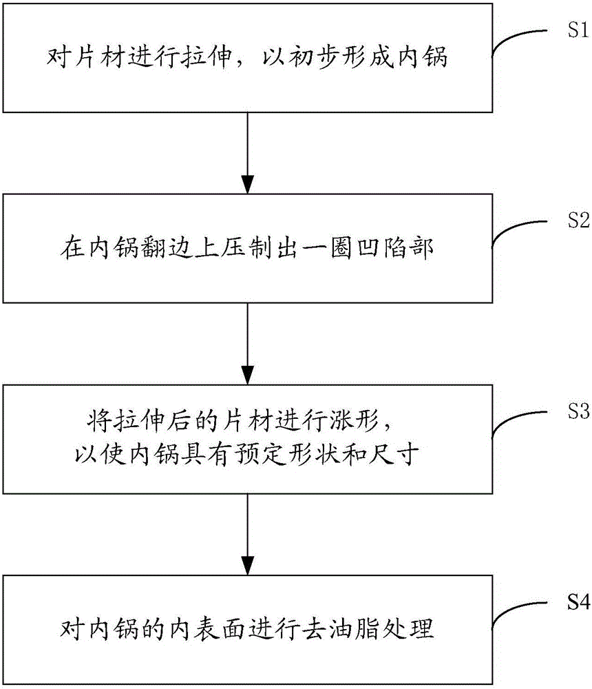
[0073] Figure 4 It is a flowchart of the manufacturing method of the inner pot according to the second preferred embodiment of the present invention. Such as Figure 4 As shown, the difference between Embodiment 2 and Embodiment 1 is that the manufacturing method of the inner pot according to this embodiment does not include step S2, and the manufacturing method of the inner pot according to this embodiment also includes after the stretching step S1 Step S5: Roll out concave-convex side wall knurling on the outer surface of the side wall by rolling, and preferably, before the stretching step S1, further include a step S0: Press the concave-convex in the middle of the sheet A plurality of bottom wall knurlings of the...
Embodiment approach 3
[0085] Refer to the following Figure 7-9 A third embodiment of the present invention will be described. For the purpose of simplification, when describing the third embodiment, the description of the same parts as the first embodiment is omitted.
[0086] Figure 7 It is a flowchart of the manufacturing method of the inner pot according to the third preferred embodiment of the present invention. Such as Figure 7 As shown, the difference between Embodiment 3 and Embodiment 1 is that the manufacturing method of the inner pot according to this embodiment does not include step S2, and the manufacturing method of the inner pot according to this embodiment further includes step S6 after step S4 : The CD pattern is turned on the upper surface of the flange of the inner pot by turning.
[0087] It can be understood that the CD pattern is an effect similar to the CD pattern obtained by removing material on the metal surface. In specific applications, the CD pattern can be obtaine...
PUM
 Abstract
Description
Claims
Application Information