Self-resetting steel framework

A self-resetting, steel frame technology, which is applied in basic structural engineering, building components, building types, etc., can solve the problems of poor self-resetting ability, cannot be repaired automatically, weak seismic performance, etc., and achieves easy construction, convenient connection, and increased consumption. performance effect

Inactive Publication Date: 2017-12-05
陈云
View PDF10 Cites 27 Cited by
  • Summary
  • Abstract
  • Description
  • Claims
  • Application Information

AI Technical Summary

Problems solved by technology

However, the traditional steel frame structure has weak seismic performance and poor self-resetting ability, and is prone to deformation and damage in earthquakes, and the damaged structure cannot be automatically repaired after the damage occurs.

Method used


Image

  • Self-resetting steel framework
  • Self-resetting steel framework
  • Self-resetting steel framework

Examples


Embodiment 1

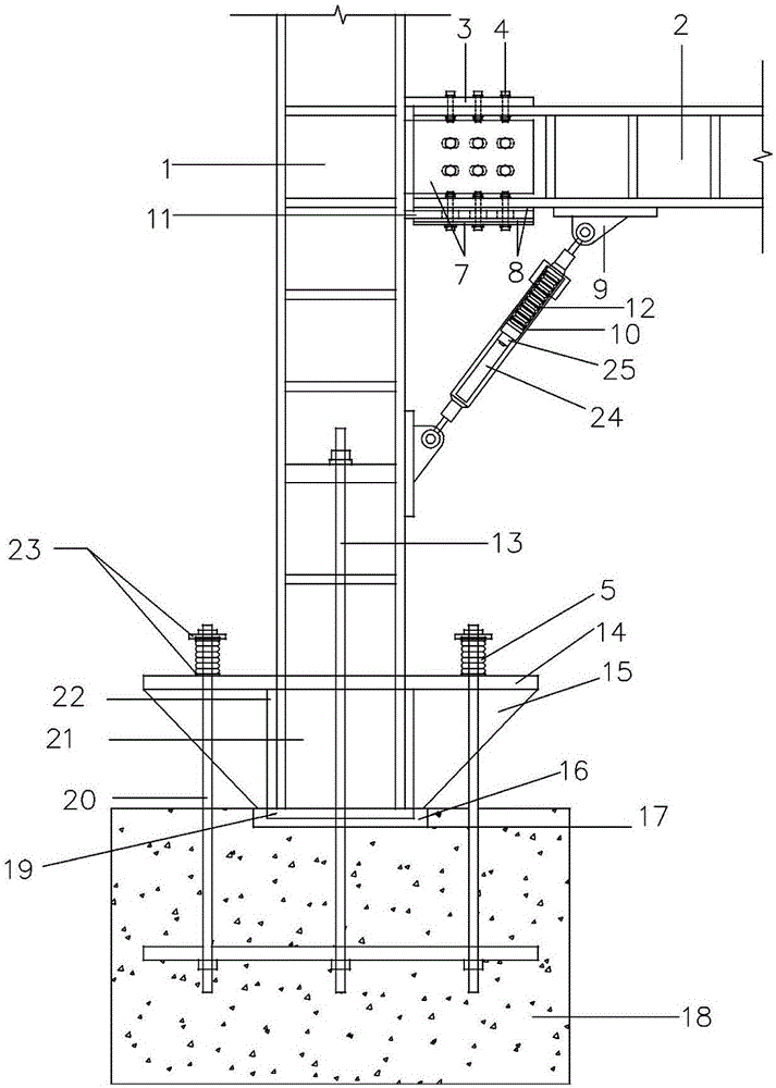
[0042] Such as Figure 1-3 As shown, the present invention provides a self-resetting steel frame, including a steel frame column 1, a steel frame beam 2, a self-resetting column foot and a self-resetting beam-column frictional energy-dissipating node, one end of the self-resetting column foot is connected to the foundation 18, and the The other end of the reset column foot is connected to one end of the steel frame column 1, and the other end of the steel frame column 1 is connected to the steel frame beam 2 through a self-resetting beam-column frictional energy dissipation node.

[0043] The self-resetting column foot includes a base plate 19, a cantilevered plate 14 and a support plate 15. A through hole is provided in the middle of the cantilevered plate 14, and the steel frame column 1 is placed on the base plate 19, the support plate 15 and the cantilevered plate through the through hole. 14, and placed in the limiting groove 17 of the foundation 18 with the bottom plate ...

Embodiment 2

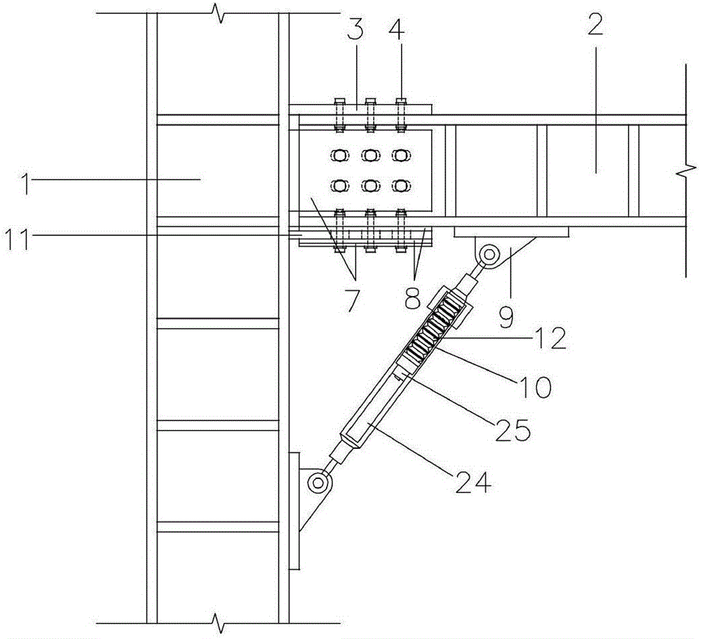
[0051] Such as Figure 4-5 As shown, a friction backing plate 8 is provided between the contact surface of the upper flange plate 3 and the steel frame beam 2, and a friction backing plate 8 is also provided between the contact surface of the upper flange plate 3 and the head of the high-strength bolt 4; A steel plate 7 is arranged between the plane where the friction pad 8 contacts the head of the high-strength bolt 4 . The connection position between the lower flange plate 11 and the steel frame beam 2 is not provided with a friction backing plate 8, and other parts are the same as in the first embodiment.

Embodiment 3

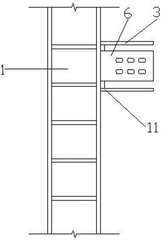
[0053] Such as Figure 6-7 As shown, the flange stiffener 22 is located inside the flange of the steel frame column 1 . Other parts are the same as embodiment one.


PUM


Abstract

The invention discloses a self-resetting steel framework comprising a steel framework column, a steel framework beam, a self-resetting column foot and a self-resetting beam-column friction energy consumption joint. One end of the self-resetting column foot is connected with a foundation, the other end of the self-resetting column foot is connected with one end of the steel framework column, and the other end of the steel framework column is connected with the steel framework beam through the self-resetting beam-column friction energy consumption joint; and the connecting position of the steel framework beam and the steel framework column can make horizontal displacement when bearing the external force effect. According to the self-resetting steel framework, earthquake energy can be dissipated through the self-resetting column foot and the self-resetting beam-column friction energy consumption joint, the energy consumption performance of the overall structure is improved significantly, self-resetting force can be provided, and the self-resetting steel framework can return to the initial state when an earthquake occurs. The self-resetting steel framework is convenient to connect and easy to construct and has high energy consumption capacity and self-resetting capacity.

Description

technical field [0001] The invention relates to the technical field of anti-seismic devices, in particular to a self-resetting steel frame. Background technique [0002] my country is a country prone to earthquakes, and has high requirements for the seismic performance of building structures. Especially, there are many high-rise and super high-rise buildings at present, and the seismic problems are more prominent. In recent years, recoverable functional structures have become a research hotspot and have attracted much attention. [0003] Steel structures have the advantages of high strength, good seismic performance, and short construction period, and are widely used in various building structures. However, the traditional steel frame structure has weak anti-seismic performance and poor self-resetting ability, and is prone to deformation and damage during earthquakes, and the damaged structure cannot be automatically repaired after the damage occurs. [0004] Therefore, re...

Claims


Application Information

Patent Timeline
Patent Type & Authority Applications(China)
IPC IPC(8): E04H9/02E04B1/24E04B1/58E04B1/98E02D27/42
CPCE04H9/02E04B1/24E04B1/2403E04B2001/2406E04B2001/2418E04B2001/2439E04B2001/2463E04H9/021E04H9/024
Inventor 陈云应琪刘涛
Owner 陈云
Why Eureka
Try Eureka