
Visual automatic detection system and detection method thereof

An automatic detection and automatic control system technology, applied in the direction of optical testing flaws/defects, analyzing materials, instruments, etc., can solve problems such as low detection efficiency, inconsistent standards, and inadequate assembly, so as to achieve high detection efficiency and ensure factory quality Effect

Pending Publication Date: 2017-12-05
LIUZHOU GENERATOR AUTOMOTIVE ELECTRICAL SYST MFR
View PDF24 Cites 7 Cited by
  • Summary
  • Abstract
  • Description
  • Claims
  • Application Information

AI Technical Summary

Problems solved by technology

At present, the appearance and quality inspection of products are all detected by human eyes, because the judgment of human eyes is not easy to quantify and execute, human eyes are prone to fatigue, people are prone to emotional, and some high temperature or toxic environments cannot work for a long time, etc. Factors, resulting in the general misjudgment and misjudgment rate of product appearance and shape quality inspection are very high
Some places have tried to use cameras to obtain images to replace human eye detection, but they all manually put a single product directly on the workbench for photo inspection, take it away after inspection, and put a new one, so repeat, automation The degree is low, the detection efficiency is low, the work intensity of the detection personnel is high, and the detection accuracy is poor, which cannot meet the needs of modern high-speed automated production lines
[0003] The types and styles of automobiles are becoming more and more diverse. In the production process of existing generators, due to the large number of product models, parts will be mixed, missing, and assembled in the assembly process.
Detection by human eyes is inefficient, the standards are not uniform, and the detection results are difficult to guarantee; and long-term detection greatly increases the labor intensity of workers

Method used


Image

  • Visual automatic detection system and detection method thereof
  • Visual automatic detection system and detection method thereof

Examples


Embodiment 1

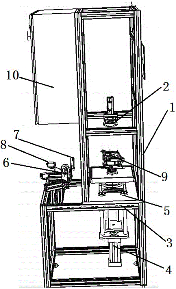
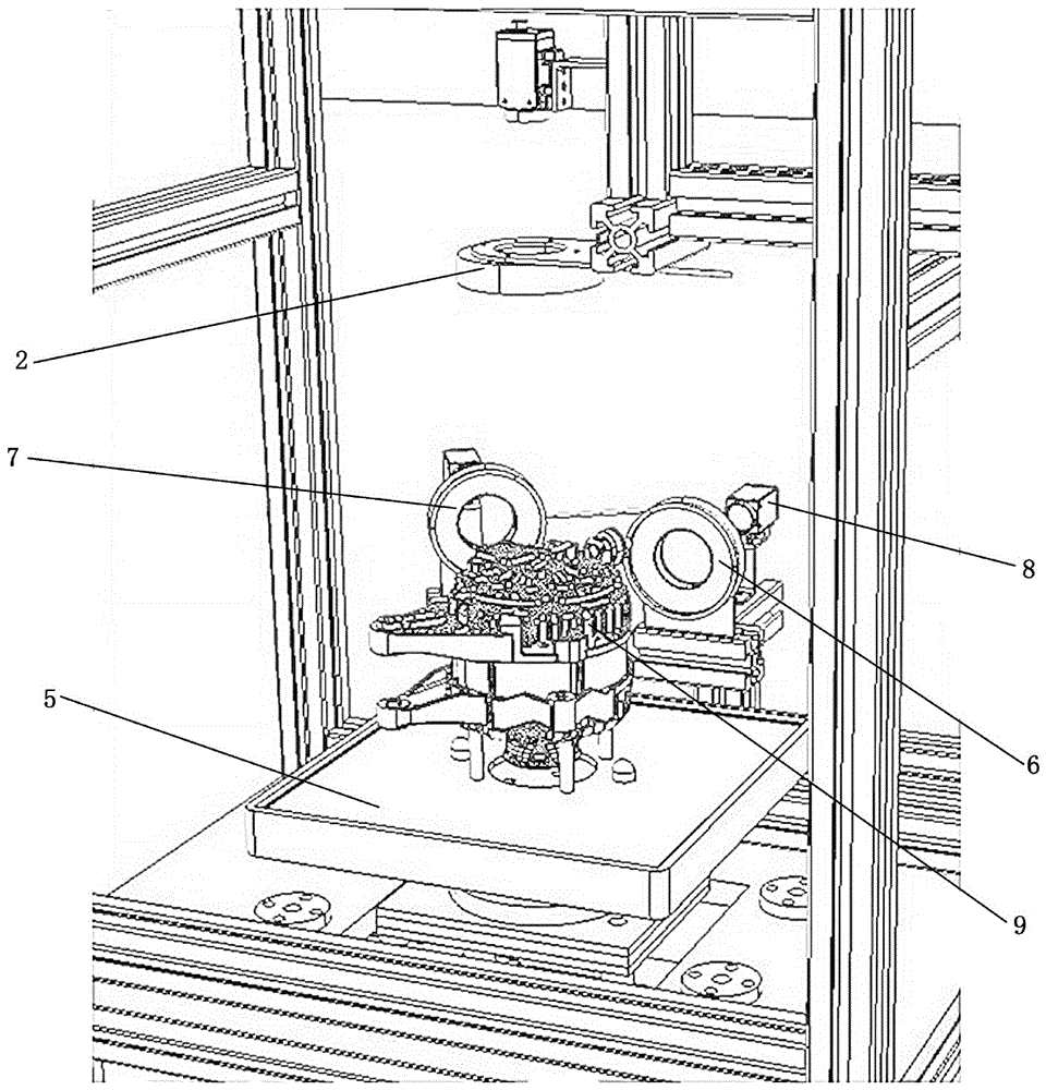
[0032] See figure 1 , figure 2 , a visual automatic inspection system, comprising a visual automatic inspection device body 1, said device body 1 including a first camera 2 arranged on the top of the device body for taking photos of bridge solder joints for detection and arrangement, an electrical cabinet 10 is arranged above the first camera, The controller and the PLC automatic control system are installed in the electrical cabinet 10. The bottom of the device body 1 is provided with a jacking and rotating device 3 that lifts and rotates the workpiece to be detected. The jacking and rotating device 3 includes a lower jacking cylinder 4 and a The upper rotating platform 5 is equipped with a second camera 6 for detecting whether the bolts are tightened in place and a third camera 7 for detecting whether the generator belts are mixed. The first camera 2, the second Camera 6 and the 3rd camera 7 rear parts are all provided with the light source 8 that is used to promote the li...


PUM


Abstract

The invention relates to the technical field of automatic mechanical apparatuses, and concretely relates to a visual automatic detection system. The visual automatic detection system comprises a visual automatic detection device body (1), the device body (1) comprises a first camera (2) arranged at the upper part of the device body (1) and used for shooting, detecting and collating pictures of a bridge welding spot, the bottom of the device body (1) is provided with a lifting and rotating unit (3) for lifting and rotating a workpiece (9) to be detected, and the lifting and rotating unit (3) comprises a lower lifting cylinder (4) and an upper rotating platform (5). The detection method of the automatic visual inspection device has a higher detection efficiency than the prior art, and the detection device can automatically shoot and analyze the product and directly output a detection result without artificial intervention, so the defects of low efficiency and high misjudgement rate of traditional human eye detection are overcome in the invention.

Description

technical field [0001] The invention relates to the technical field of automatic mechanical equipment, in particular to a visual automatic detection system and a detection method thereof. Background technique [0002] With the development of society and the continuous progress of science and technology, coupled with the increasing consumption level, it will become a trend to use automation equipment to reduce labor intensity, improve product quality, and reduce risks in the manufacturing process. At present, the appearance and quality inspection of products are all detected by human eyes, because the judgment of human eyes is not easy to quantify and execute, human eyes are prone to fatigue, people are prone to emotional, and some high temperature or toxic environments cannot work for a long time, etc. Factors, resulting in the general misjudgment and misjudgment rate of the quality inspection of product appearance and shape. Some places have tried to use cameras to obtain ...

Claims


Application Information

Patent Timeline
Patent Type & Authority Applications(China)
IPC IPC(8): G01N21/95G01N35/00
CPCG01N21/95G01N35/00712
Inventor 林启兴
Owner LIUZHOU GENERATOR AUTOMOTIVE ELECTRICAL SYST MFR
Learn More