

Robot positioning method based on infrared lamp three-dimensional arrays
A robot positioning and infrared light technology, applied in positioning, instruments, radio wave measurement systems, etc., can solve the problems of deviation and low positioning accuracy, and achieve the effect of avoiding distortion and error, accurate positioning, and high positioning accuracy.
- Summary
- Abstract
- Description
- Claims
- Application Information
AI Technical Summary
Problems solved by technology
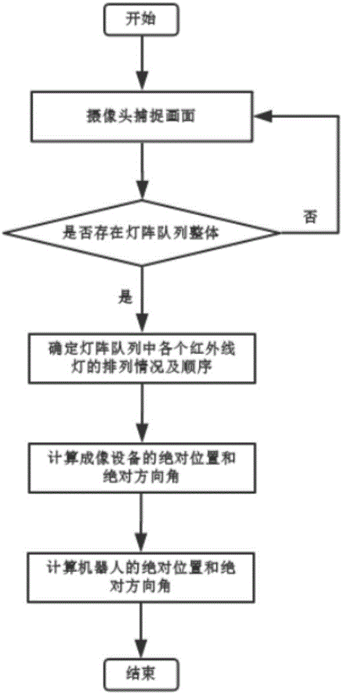
Method used
Image

Examples
Embodiment 1
[0108] Embodiment 1, as a specific implementation mode, will be described for step S3 to illustrate and explain the technical means of the present invention, but does not limit the scope of protection of the present invention.
[0109] In the infrared lamp array queue area determined based on sub-step S31, set any two circular contour centers as (x k ,y k ) and (x k+1 ,y k+1 ), the image pixel distance d between them k , d k It can be calculated by the following formula:
[0110]
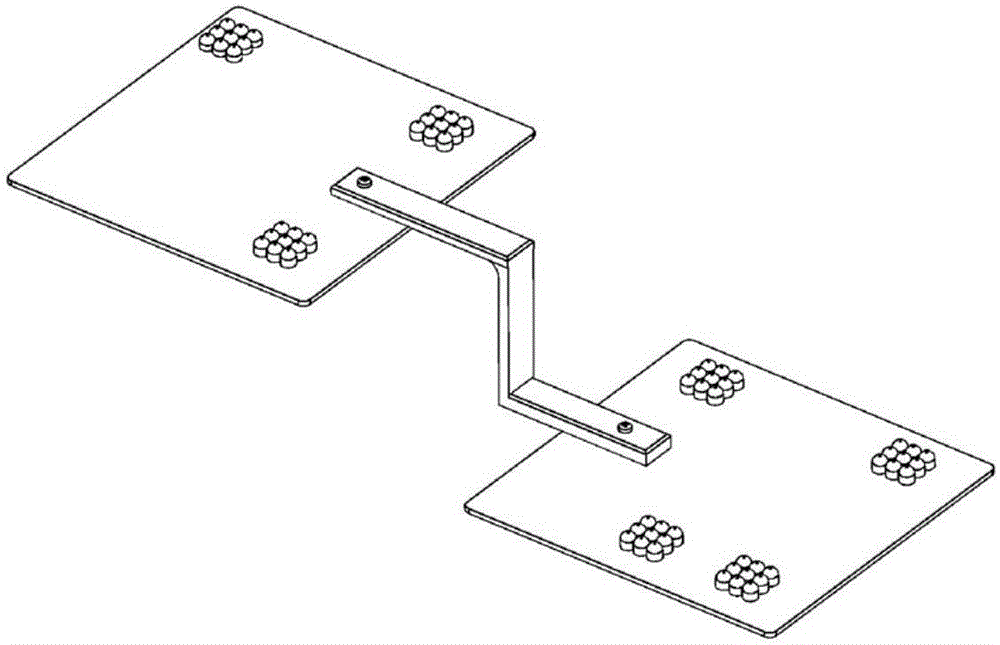
[0111] The line connecting two points with the longest distance is used as the reference line L, which divides the infrared lamp array into two parts. The upper right part of the reference line L is used as the upper part, and the lower left part of the reference line L is used as the lower part. In the upper part, there are n circular contours except the two circular contours on the reference line L, and in the lower part, except for the two circles on the reference line L There are m circ...
Embodiment 2
[0116] Embodiment two, as another kind of implementation mode, set the image pixel coordinates of the centers of the two circular contours on the reference line L as A(x a ,y a ) and B(x b ,y b ), with n=2 in the upper half of the reference line L, take i as C or D, and the image pixel coordinates are (x C ,y C ) and (x d ,y d ) as an example. The order of the four circular contours can be obtained from the clockwise and counterclockwise relationship and the image pixel distance relationship. Get any point of C or D as point E, the principle is the same as that of Embodiment 1, and the calculation formula is:
[0117] k=(x e -x a )×(y b -y e )-(y e -y a )×(x b -x e )
[0118] k=0-p
[0119] Among them, p is an adjustment parameter, and the multi-point clockwise relationship can be obtained from the size relationship between k and 0-p. When k is greater than 0-p, the multi-point relationship is clockwise. The center A of the circular contour is the center of t...
PUM
 Abstract
Description
Claims
Application Information