

Optical imaging lens
An optical imaging lens and lens technology, applied in optics, optical components, instruments, etc., can solve problems such as inability to meet imaging requirements, and achieve the effect of high relative illuminance and large field of view
- Summary
- Abstract
- Description
- Claims
- Application Information
AI Technical Summary
Problems solved by technology
Method used
Image

Examples
Embodiment 1
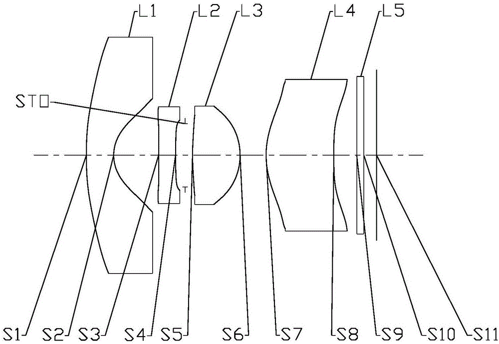
[0065] Refer to the following Figure 1 to Figure 2D An optical imaging lens according to Embodiment 1 of the present application is described. figure 1 A schematic structural diagram of an optical imaging lens according to Embodiment 1 of the present application is shown.
[0066] Such as figure 1 As shown, the optical imaging lens sequentially includes a first lens L1 , a second lens L2 , a third lens L3 , a fourth lens L4 and an imaging surface S11 along the optical axis from the object side to the imaging side. The optical imaging lens may further include a photosensitive element disposed on the imaging surface S11.
[0067] The first lens L1 has negative refractive power, the object side S1 is convex, the image side S2 is concave, and both the object side S1 and the image side S2 of the first lens L1 are aspherical.
[0068] The second lens L2 has positive refractive power, the object side S3 is convex, the image side S4 is concave, and both the object side S3 and the ...
Embodiment 2
[0090] Refer to the following Figure 3 to Figure 4D An optical imaging lens according to Embodiment 2 of the present application is described. In this embodiment and the following embodiments, for the sake of brevity, descriptions similar to those in Embodiment 1 will be omitted. image 3 A schematic structural diagram of an optical imaging lens according to Embodiment 2 of the present application is shown.
[0091] Such as image 3 As shown, the optical imaging lens sequentially includes a first lens L1 , a second lens L2 , a third lens L3 , a fourth lens L4 and an imaging surface S11 along the optical axis from the object side to the imaging side. The optical imaging lens may further include a photosensitive element disposed on the imaging surface S11.
[0092] The first lens L1 has negative refractive power, the object side S1 is convex, the image side S2 is concave, and both the object side S1 and the image side S2 of the first lens L1 are aspherical.
[0093] The sec...
Embodiment 3
[0108] Refer to the following Figure 5 to Figure 6D An optical imaging lens according to Embodiment 3 of the present application is described. Figure 5 A schematic structural diagram of an optical imaging lens according to Embodiment 3 of the present application is shown.
[0109] Such as Figure 5 As shown, the optical imaging lens sequentially includes a first lens L1 , a second lens L2 , a third lens L3 , a fourth lens L4 and an imaging surface S11 along the optical axis from the object side to the imaging side. The optical imaging lens may further include a photosensitive element disposed on the imaging surface S11.
[0110] The first lens L1 has negative refractive power, the object side S1 is concave, the image side S2 is concave, and both the object side S1 and the image side S2 of the first lens L1 are aspherical.
[0111] The second lens L2 has positive refractive power, the object side S3 is convex, the image side S4 is concave, and both the object side S3 and t...
PUM
 Abstract
Description
Claims
Application Information