Methods to spray paint on body of an inductor
A technology of inductors and bodies, applied in the field of inductors, can solve the problems of structural damage, multi-time and cost of inductor pins
- Summary
- Abstract
- Description
- Claims
- Application Information
AI Technical Summary
Problems solved by technology
Method used
Image
Examples
no. 1 example
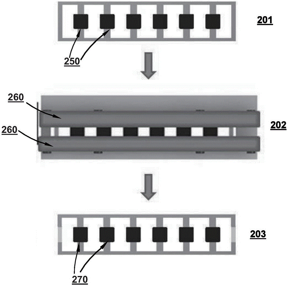
[0038] The method described in this example uses a non-adhesive tape to cover the inductor pins so that the pins can be protected when spray coating is performed on the six surfaces of the inductor body, where the coating material can be polymer and adhesive agent materials such as resins. The method described in this embodiment can be applied to pins of various sizes or shapes, and the body of the inductor can be a magnetic body.
[0039] Please refer to figure 2 , which shows a view of the step of forming a coating layer on the magnetic body of an inductor using a non-adhesive tape to cover the pins of an inductor, wherein a view 201 is shown on the magnetic body of each inductor 250 Inductor 250 is fabricated and placed on a frame before paint is applied on all surfaces; a view 202 shows the legs of inductor 250 on the frame covered by an adhesive tape 260, wherein through use there is no adhesive on its lower surface. tape 260 of composite material, the tape 260 does no...
no. 2 example
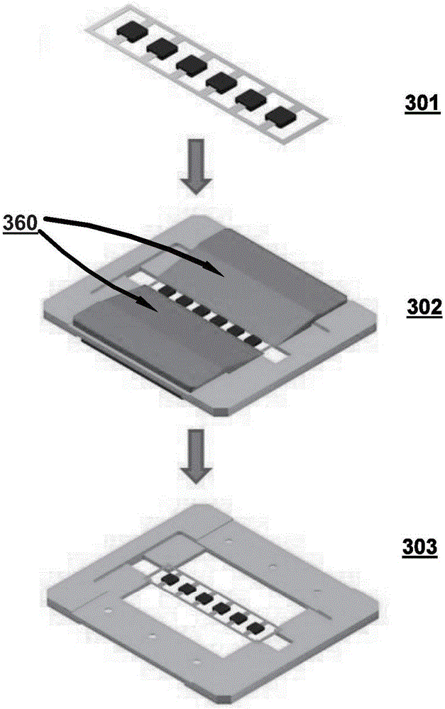
[0042]This embodiment discloses a method of forming a coating layer on a magnetic body of an inductor, the method comprising: coating a body of an inductor having a first pin, wherein the first pin extending the legs to the outside of the body, covering the first leg with a fixture, wherein the fixture is not adhered to the first leg, spraying paint on all surfaces of the inductor body, and removing the fixture to Expose the first pin.
[0043] Please refer to image 3 , which shows a view of the step of forming a coating layer on the magnetic body of the inductor using a fixture to cover the pins of an inductor, wherein a view 301 is shown on all surfaces of the magnetic body of each inductor Arranged on a frame prior to application of paint; a view 302 shows that the pins of the inductor on the frame are covered by a fixture, wherein the fixture is secured by using a fixture 360 that has no adhesive material on its lower surface. Do not adhere to the pins; then spray pai...
no. 3 example
[0046] This embodiment discloses a method for forming a coating layer on a magnetic body of an inductor, wherein a pin extends from one side surface of the inductor body, the method includes: using an ultrasonic device to spray paint On all surfaces of the inductor where the pins are not covered when the paint is applied using ultrasonic equipment.
[0047] Please refer to Figure 4 , which shows the views of the steps of forming a coating layer on the magnetic body of an inductor, wherein a view 401 shows that it is arranged on a frame before spraying paint on all surfaces of the magnetic body of each inductor; View 402 shows that the pins of the inductor on the frame are not covered by anything; the paint 450 is then sprayed onto the magnetic body by using an ultrasonic device to coat all surfaces of the magnetic body of the inductor, which can Creates an air wall to control spray coverage so pins are not coated. The paint can be anti-rust or insulating paint, and the ultr...
PUM
 Abstract
Description
Claims
Application Information
 - R&D
- Intellectual Property
- Life Sciences
- Materials
- Tech Scout
- Unparalleled Data Quality
- Higher Quality Content
- 60% Fewer Hallucinations
Browse by: Latest US Patents, China's latest patents, Technical Efficacy Thesaurus, Application Domain, Technology Topic, Popular Technical Reports.
© 2025 PatSnap. All rights reserved.Legal|Privacy policy|Modern Slavery Act Transparency Statement|Sitemap|About US| Contact US: help@patsnap.com


