A Spindle Head Mechanism of In-situ Backfill Friction Stir Spot Welding

A friction stir and spindle head technology, applied in welding equipment, non-electric welding equipment, metal processing equipment, etc., can solve the problems of friction spot welding joint mechanical properties, uneven heating of stirring tools, insufficient plastic flow, etc., to promote Wide application, flexible processing and low manufacturing cost

Inactive Publication Date: 2019-04-23
TIANJIN HUANBO SCI & TECH CO LTD
View PDF7 Cites 0 Cited by
  • Summary
  • Abstract
  • Description
  • Claims
  • Application Information

AI Technical Summary

Problems solved by technology

[0007] However, there are still the following main problems in RFSSW technology in industrial promotion and application: 1) Compared with traditional resistance spot welding equipment, RFSSW equipment obviously has high investment costs, which seriously hinders its popularization and application
The core of the RFSSW process is the friction stir spot welding tool and the spindle head mechanism, which requires the precise control of multiple servo motors to realize the process principle of in-situ backfilling, which makes the spindle head mechanism and control process of the equipment very complicated, coupled with the limitation of patented technology The manufacturing cost of RFSSW equipment is obviously high; 2), the uneven heating of the stirring tool is easy to produce spot welding ring defects
Since the tightening ring of the stirring tool is stationary, while the intermediate sleeve and the stirring pin rotate at high speed and frictionally heat the workpiece, obvious heating unevenness occurs on the contact surface between the tightening ring and the intermediate sleeve and the workpiece. When the intermediate sleeve moves up and down, it will be welded Insufficient plastic flow occurs around the nuclei, resulting in the formation of annular defects around the nugget, which will have a serious impact on the mechanical properties of friction spot welded joints

Method used


Image

  • A Spindle Head Mechanism of In-situ Backfill Friction Stir Spot Welding
  • A Spindle Head Mechanism of In-situ Backfill Friction Stir Spot Welding
  • A Spindle Head Mechanism of In-situ Backfill Friction Stir Spot Welding

Examples


Embodiment Construction

[0043] The technical solution of the present invention will be further described in detail below in conjunction with the accompanying drawings and specific embodiments, and the described specific embodiments are only for explaining the present invention, and are not intended to limit the present invention.

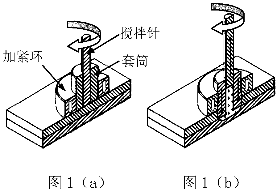
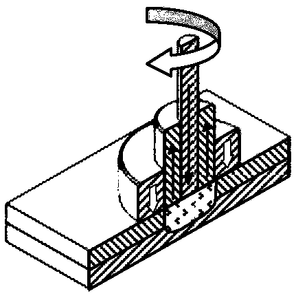
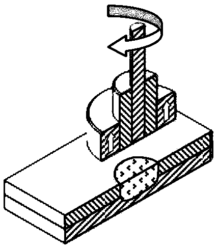
[0044] The design concept of the in-situ backfill friction stir spot welding spindle head mechanism proposed by the present invention is to propose a completely different spindle head motion control mechanism in the current RFSSW equipment in view of the limitations of the current RFSSW equipment spindle head mechanism. The spindle head mechanism adopts the hollow spindle nesting method, that is, the central shaft of the stirring needle is sleeved in the middle sleeve shaft, and the middle sleeve shaft is sleeved in the hollow shaft of the external clamping ring. Through the nesting method of three layers of hollow shafts, and then Use the servo motor to control the three-l...


PUM


Abstract

The invention discloses an in-situ backfilling type friction stirring spot welding main shaft head mechanism. The in-situ backfilling type friction stirring spot welding main shaft head mechanism is composed of two parts, one part includes a body structure hollow main shaft sleeve, and the other part includes an upper fixing shaft sleeve and an outer layer lower fixing sleeve, wherein the body structure hollow main shaft sleeve is connected with a machine tool rotation power main shaft and can rotate at a high speed, and the upper fixing shaft sleeve and the outer layer lower fixing sleeve are connected with the machine tool main shaft fixing part. The two parts (inner rotation and outer fixation) are integrated together to form the main shaft head mechanism through four pairs of angular bearings and other components. The main shaft head mechanism is an independent mechanical movement mechanism, and the whole technology process of in-situ backfilling friction spot welding (RFSSW) can be achieved. The in-situ backfilling type friction stirring spot welding main shaft head mechanism is simple in structure and easy to maintain, a stirring tool of the in-situ backfilling type friction stirring spot welding main shaft head mechanism can be conveniently dismounted, replaced and mounted. The main shaft head mechanism and a plain milling machine power main shaft are combined, the whole technology process of RFSSW can be achieved, accordingly, the manufacturing cost of RFSSW equipment is effectively reduced, and an important basis is provided for wide application and popularization of the RFSSW technology.

Description

technical field [0001] The invention belongs to the technical field of solid-phase friction welding, and in particular relates to a spindle head mechanism for realizing an in-situ backfilling friction stir spot welding process. Background technique [0002] In-situ refill friction stir spot welding (Refill Friction Stir Spot Welding-RFSSW) is an innovative solid phase friction spot welding technology developed by the German GKSS Research Center in 1999. After using this method for aluminum alloy spot welding, the surface of the weld seam is smooth, and there is no concave hole in the center of the welding spot, and the appearance of the spot weld seam is similar to that of the traditional resistance spot weld seam. Therefore, it has broad application prospects in the field of lightweight aluminum alloy structure manufacturing, such as aviation, aerospace and automobile industry. [0003] The principle of RFSSW process is shown in Figure 1(a), Figure 1(b), Figure 1(c) and Fi...

Claims


Application Information

Patent Timeline
IPC IPC(8): B23K20/12
CPCB23K20/1245
Inventor 杨新岐李建波秦红珊
Owner TIANJIN HUANBO SCI & TECH CO LTD
Why Eureka
Try Eureka