Guide rail for automatic welding equipment

An automatic welding and equipment technology, applied in welding equipment, auxiliary welding equipment, welding/cutting auxiliary equipment, etc., can solve the problems of scattered setting and assembly trouble, and achieve the effect of improving assembly efficiency

Inactive Publication Date: 2017-12-08
黄石启新智能科技有限公司
View PDF0 Cites 1 Cited by
  • Summary
  • Abstract
  • Description
  • Claims
  • Application Information

AI Technical Summary

Problems solved by technology

[0004] The purpose of the present invention is to solve the shortcomings of the prior art that the components of the guide rail for automatic welding equipment are scattered and the assembly is troublesome, and propose a guide rail for automatic welding equipment

Method used


Image

  • Guide rail for automatic welding equipment
  • Guide rail for automatic welding equipment
  • Guide rail for automatic welding equipment

Examples


Embodiment Construction

[0015] The following will clearly and completely describe the technical solutions in the embodiments of the present invention with reference to the accompanying drawings in the embodiments of the present invention. Obviously, the described embodiments are only some, not all, embodiments of the present invention.

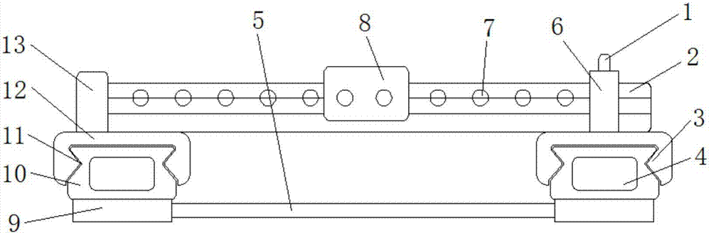
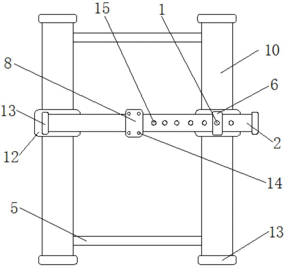
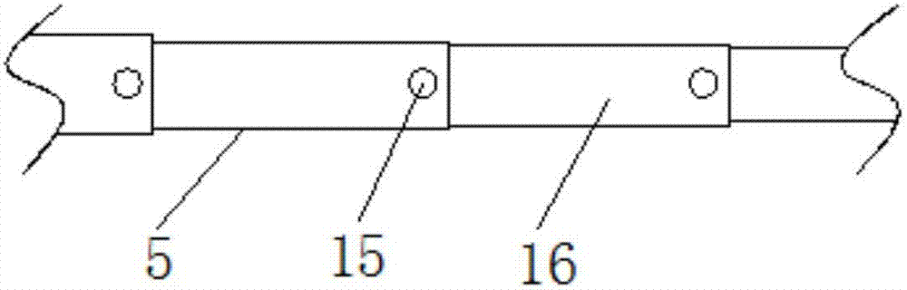
[0016] refer to Figure 1-3 , a guide rail for automatic welding equipment, including a group of first slide rails 10 arranged in parallel, a base 9 is fixed at the bottom of the first slide rail 10, and the two bases 9 are connected by a connecting rod 5, and the connecting rod 5 is composed of a plurality of The sleeves 16 are nested with each other, and each sleeve 16 has a pin hole 15 at both ends, and the two adjacent sleeves 16 are fixed by inserting the fixed pin 1 into the corresponding pin hole 15. A slide rail 10 is provided with a first slide 12, one of the first slide 12 is fixed with a second slide 2, and the other first slide 12 is fixed with a U-shaped...


PUM


Abstract

The invention relates to the field of automatic welding technology, in particular to a guide rail for automatic welding equipment, which includes a group of first slide rails arranged in parallel, a base is fixed at the bottom of the first slide rail, and the two bases are connected by a connecting rod. It consists of a plurality of sleeves nested with each other. The first slide rail is provided with a first sliding seat, one of the first sliding seats is fixed with a second slide rail, and the other first sliding seat is fixed with a U-shaped sleeve. The second sliding rail is arranged parallel to the connecting rod, the U-shaped sleeve is sleeved on the outside of the second sliding rail, and a pre-tightening mechanism is provided between the U-shaped sleeve and the second sliding rail, and the second sliding seat is arranged on the second sliding rail. Both sides of the first sliding seat and the second sliding seat are provided with sliding bars, both sides of the first sliding rail and the second sliding rail are provided with chute grooves, and the sliding bars are slidably connected in the corresponding chute grooves, and the upper end of the second sliding seat is opened. There are mounting holes. The invention has simple structure and convenient use, and greatly improves the assembly efficiency of the guide rail of the welding equipment.

Description

technical field [0001] The invention relates to the technical field of automatic welding, in particular to a guide rail for automatic welding equipment. Background technique [0002] In recent years, with the development of digitization, automation, computer and mechanical design technology, and the high emphasis on welding quality, automatic welding has developed into an advanced manufacturing technology, and the role played by automatic welding equipment in the application of various industries Increasingly, the scope of application is rapidly expanding. In modern industrial production, the mechanization and automation of the welding production process is an inevitable trend in the modernization of the welding mechanism manufacturing industry. [0003] Existing automatic welding equipment generally needs to be equipped with a special guide rail mechanism to complete the walking track of the welding head, but most of the existing guide rails for automatic welding equipment...

Claims


Application Information

Patent Timeline
IPC IPC(8): B23K37/02
CPCB23K37/0211
Inventor 程敏吕增智
Owner 黄石启新智能科技有限公司
Why Eureka
Try Eureka