Hoisting tool and process for large connective corridor steel structure

A hoisting tool, steel structure technology, applied in transportation and packaging, load hanging components, cranes, etc., can solve the problems of danger, low efficiency, difficult hoisting of large-scale connecting beam steel structures, etc., to achieve high reliability, convenient and flexible operation , The effect of high degree of equipment automation

Pending Publication Date: 2017-12-08
CHINA CONSTR SECOND ENG BUREAU LTD
View PDF9 Cites 10 Cited by
  • Summary
  • Abstract
  • Description
  • Claims
  • Application Information

AI Technical Summary

Problems solved by technology

[0003] The purpose of the present invention is to provide hoisting tools and hoisting techniques for large-scale corridor steel structures, so as t

Method used


Image

  • Hoisting tool and process for large connective corridor steel structure
  • Hoisting tool and process for large connective corridor steel structure
  • Hoisting tool and process for large connective corridor steel structure

Examples


Embodiment 1

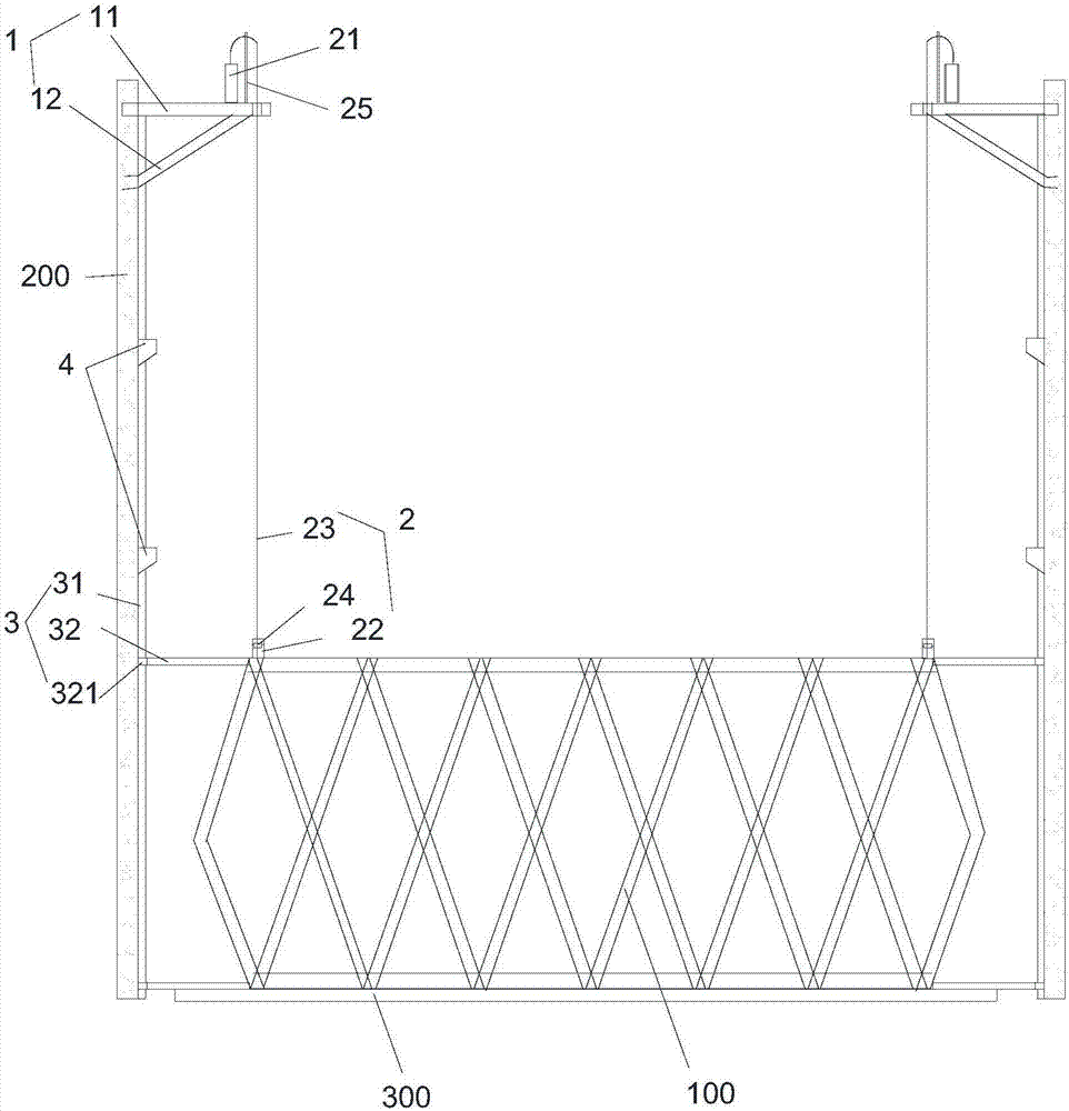
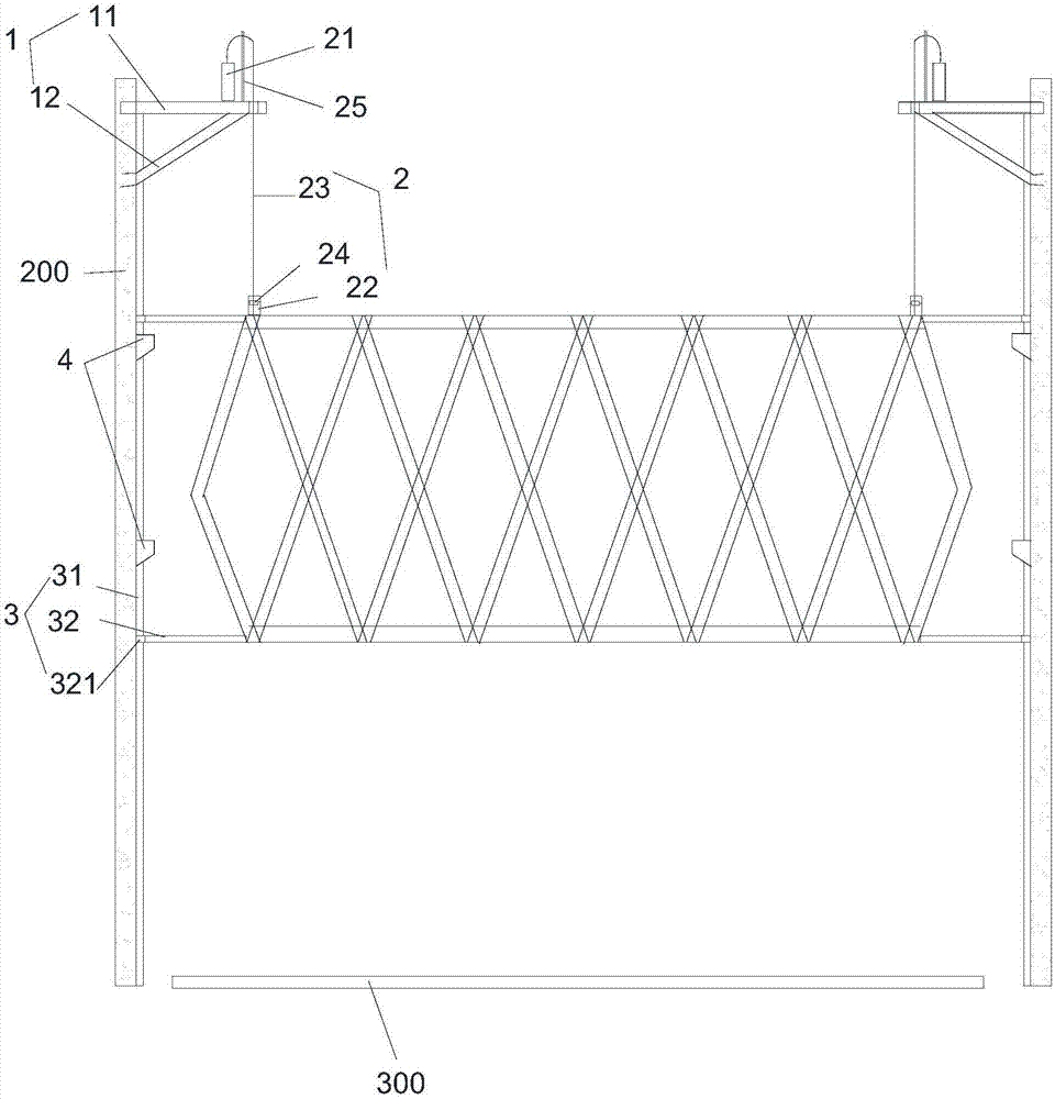
[0043] Such as figure 1 As shown, the present invention provides a hoisting tool for a large-scale corridor steel structure, including a lifting bracket 1, a lifting device 2, a lifting limit device 3 and a control system. The lifting bracket 1 is arranged above the steel structure 100 to be installed; the lifting device 2 is installed on the lifting bracket 1, and the output end of the lifting device 2 is connected to the steel structure 100; the number of lifting limit devices 3 is at least two, and all the lifting limit devices 3 are detachably connected to the steel structure 100 to be lifted ; The control system is electrically connected with the lifting device 2 and the lifting limit device 3 . The lifting limit device 3 is used to limit the steel structure 100 in the horizontal direction to prevent the steel structure 100 from shaking in the air. The large-scale corridor steel structure 100 is installed between two buildings. The number of lifting brackets 1 is an even...

Embodiment 2

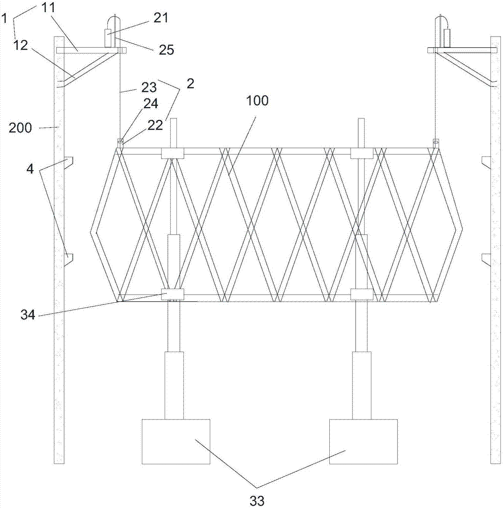
[0070] Such as image 3 As shown, compared with Embodiment 1, the present embodiment differs only in the structure of the lifting and limiting device. The lifting and limiting device 3 is installed on the front and rear sides of the steel structure 100 on the side perpendicular to the plane of the building. The lifting limit device includes an electric telescopic column set on the ground and a limit sleeve set on the steel structure. There are multiple telescopic joints of the electric telescopic column; when all the telescopic joints of the electric telescopic column are extended, The height of the electric telescopic column is the same as that of the lifting bracket from the ground, and the limit sleeve is a hollow cylindrical structure, and the limit sleeve is set on the electric telescopic column. When carrying out hoisting operations, the electric telescopic column is set on the ground, and then the sleeve is set on the telescopic joint rod of the electric telescopic colu...


PUM


Abstract

The invention provides a hoisting tool and process for a large connective corridor steel structure, relates to the technical field of construction equipment and solves the technical problems that a large steel structure cannot be wholly hoisted and a hoisting process is not safe enough and is affected greatly by the environment. The hoisting tool comprises a lifting bracket, a lifting device, at least two lifting limit devices and a control system, wherein the lifting bracket is arranged above a position where the steel structure is to be mounted; the lifting device is mounted on the lifting bracket, and an output end of the lifting device is connected with the steel structure; all the lifting limit devices are connected with the to-be-lifted steel structure; the control system is electrically connected with the lifting device and the lifting limit devices. The hoisting tool has the characteristics of being high in automation degree and reliability, flexible and convenient to operate, good in safety, little in aerial work, time-saving, labor-saving and short in construction consumed time.

Description

technical field [0001] The invention relates to the technical field of building construction equipment and construction technology, in particular to a large-scale corridor steel structure hoisting tool and hoisting technology, which is suitable for tower crane tonnage restrictions, large-scale crane equipment and on-site operating conditions that do not match, and super-high, The construction and operation of the overall lifting and installation of oversized and overweight large steel structures. Background technique [0002] With the expansion of economic and cultural construction needs and the improvement of people's appreciation of architecture, large-span steel structures are more and more favored by designers due to their diverse forms, beautiful appearance, and good economy. Spatial structures are mainly applied to the roof structures of large public buildings such as airport buildings, convention and exhibition centers, stadiums, and exhibition halls. The new charact...

Claims


Application Information

Patent Timeline
IPC IPC(8): B66C25/00B66C13/06
CPCB66C13/06B66C25/00
Inventor 朱登石峰邓辉范辉林曹云
Owner CHINA CONSTR SECOND ENG BUREAU LTD
Why Eureka
Try Eureka