Cast-in-situ thermal-insulation integrated slope roof structure and construction method

A sloping roof and integrated technology, which is applied in the field of cast-in-place thermal insulation integrated sloping roof structure and construction, can solve the problems of difficult roof detail processing, complex construction technology, complex decoration structure, etc. The effect of firm connection and low labor intensity

Pending Publication Date: 2017-12-08
廊坊卓锐建材有限公司
View PDF4 Cites 3 Cited by
  • Summary
  • Abstract
  • Description
  • Claims
  • Application Information

AI Technical Summary

Problems solved by technology

The problems of this structure form are: high cost, great difficulty in the detailed treatment of the roof, complicated roof decoration structure and difficult construction
The problems of this structure form are: the construction process is complex, the amount of wood is large, the cost is high, and the roof decoration structure is also complicated in the later stage, and the construction is difficult; the broken roof of the above two structures cannot fundamentally solve the problem of heat insulation and fire protection Therefore, the present invention provides a cast-in-place integrated sloping roof structure with simple construction technology, fast construction efficiency and long service life, which fundamentally solves the problem of heat insulation and leakage prevention.

Method used


Image

  • Cast-in-situ thermal-insulation integrated slope roof structure and construction method
  • Cast-in-situ thermal-insulation integrated slope roof structure and construction method
  • Cast-in-situ thermal-insulation integrated slope roof structure and construction method

Examples


Embodiment 1

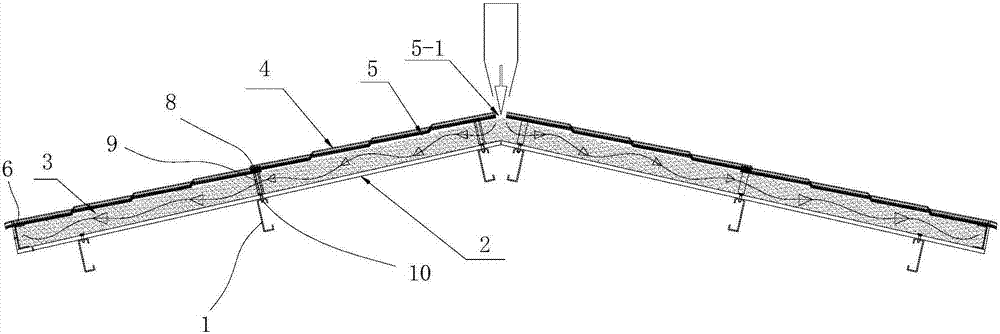
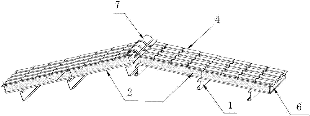
[0035] Example 1, see figure 1 and 2 , a cast-in-place thermal insulation integrated sloping roof structure, comprising purlins 1, an interior decoration carrier 2, an insulation layer 3 and roof tiles 4; the interior decoration carrier is fixedly connected to the purlin 1, above the interior decoration carrier Roof tiles 4 are installed through support members, the decorative carrier and roof tiles are at least equal to the span between two adjacent purlins in the length direction, and an insulation layer accommodation cavity 5 is formed between the interior decoration carrier and roof tiles, A plugging plate 6 is fixedly installed between the bottom of the insulation layer accommodation cavity and between the side roof tiles and the interior decoration carrier. The upper part of the insulation layer accommodation cavity is an open structure, forming a cast-in-place insulation layer pouring port 5-1, and the pouring is completed. Finally, the roof ridge cover plate 7 is fixe...

Embodiment 2

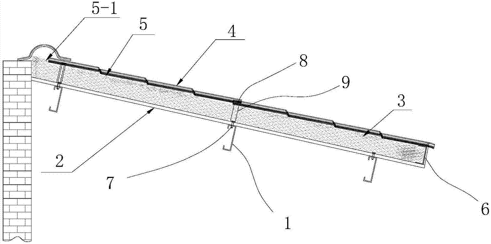
[0039] Embodiment 2, this embodiment is also suitable for mono-pitch roofs, such as image 3 .

Embodiment 3

[0040] Example 3, see Figure 4 , preferably in this embodiment, the interior decoration carrier 2 is installed on the lower surface of the purlin 1 through the third fastening screw 11; the upper surface of the purlin is laid with roof tiles 4, and the roof tile is passed through the fourth The fastening screw 12 is fixedly connected with the purlin 1 . All the other structures are the same as in Example 1.


PUM


Abstract

The invention relates to a cast-in-situ thermal-insulation integrated slope roof structure. The cast-in-situ thermal-insulation integrated slope roof structure is characterized in that a roof comprises purline, inner decoration bearing bodies, a thermal-insulation layer and roof tiles, wherein the inner decoration bearing bodies are fixedly connected with the purlines, the roof tiles are mounted above the inner decoration bearing bodies through support components, the lengths of the inner decoration bearing bodies and the roof tiles are at least equal to the span between two adjacent purlines, a thermal-insulation layer accommodating cavity is formed between the inner decoration bearing bodies and the roof tiles, sealing plates are mounted between the bottom of the thermal-insulation layer accommodating cavity and the lateral roof tiles and between the bottom of the thermal-insulation layer accommodating cavity and the inner decoration bearing bodies, the upper portion of the thermal-insulation layer accommodating cavity is of an open structure to form a cast-in-situ thermal-insulation layer pouring opening, and a ridge cover plate is fixedly mounted above the cast-in-situ thermal-insulation layer pouring opening after pouring. The invention further discloses a construction method based on the cast-in-situ thermal-insulation integrated slope roof structure. The cast-in-situ thermal-insulation integrated slope roof structure is simple in process, high in construction efficiency, long in service life, capable of fundamentally achieving thermal insulation and leakage prevention, and the like.

Description

technical field [0001] The invention belongs to the technical field of building sloping roofs in the construction industry, and in particular relates to a cast-in-place thermal insulation integrated sloping roof structure and a construction method. Background technique [0002] At present, the problem of heat insulation and leakage prevention of the roof has always been a headache in the construction industry. It is one of the effective methods to add a sloping roof to the roof. In the prior art, there are two common sloping roof structures, One is the steel structure slope roof: use H or C-shaped steel inclined beams (or use angle steel to make the roof truss), use C-shaped steel purlins to lay on the steel inclined beams, and then cover the tile surface. The problems of this structural form are: high cost, great difficulty in detailing the roof, complicated roof decoration structure and difficult construction. The other is a wooden sloping roof: bricks or cast-in-place co...

Claims


Application Information

Patent Timeline
Patent Type & Authority Applications(China)
IPC IPC(8): E04B7/02E04D1/02E04D13/16
CPCE04B7/024E04D1/02E04D13/1618
Inventor 张国营
Owner 廊坊卓锐建材有限公司
Why Eureka
Try Eureka