
A Tool to Prevent Overtorque on Drill Bits
An oversized tool technology, which is applied in the field of tools to prevent excessive torque of the drill bit, and can solve problems such as low ROP, affecting drilling efficiency, and chipped teeth of the drill bit
- Summary
- Abstract
- Description
- Claims
- Application Information
AI Technical Summary
Problems solved by technology
Method used
Image

Examples
Embodiment Construction
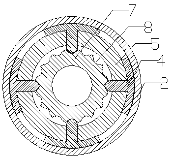
[0019] The tool for preventing excessive torque of the drill bit includes an upper joint 1, a disc spring 3, a cone sleeve 2, a push piece 4, a transmission shaft 5 and an output shaft 7; There is output shaft 7. The transmission shaft 5 and the output shaft 7 are reducing bodies respectively, and a seal 6 is arranged between the transmission shaft 5 and the output shaft 7 to prevent impurities in the wellbore from entering the drilling fluid flow path from between the transmission shaft 5 and the output shaft 7 .
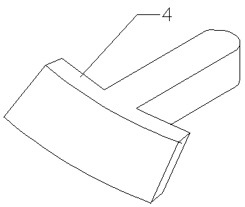
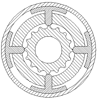
[0020] The transmission shaft 5 is covered with a tapered sleeve 2, and a disc spring 3 is arranged between the tapered sleeve 2 and the upper joint 1. Mounting holes are evenly distributed on the circumference of the upper end of the transmission shaft 5, and push pieces 4 are movable in the mounting holes. There are four mounting holes and four push pieces 4 respectively.
[0021] The push piece 4 is T-shaped; the output shaft 7 corresponding to the push piece 4...
PUM
 Abstract
Description
Claims
Application Information