Rotary shaft type gas valve engine

An engine and air valve technology, which is applied in the direction of engine components, machines/engines, mechanical equipment, etc., can solve problems such as low inflation efficiency, loud noise, and complex structure, and achieve reduction of reciprocating inertia force, reduction of vibration noise, and simplified structure Effect

Pending Publication Date: 2017-12-08
ZHUHAI COLLEGE OF JILIN UNIV
View PDF7 Cites 0 Cited by
  • Summary
  • Abstract
  • Description
  • Claims
  • Application Information

AI Technical Summary

Problems solved by technology

There are valve seats, intake and exhaust passages, cooling water passages, etc. on the cylinder head, so the structure is very complicated, and it is also very difficult for processing
[0004] Over the years, many types of engine valve trains have been developed, but the overall structural form has not changed. The commonly used two forms are side valve and overhead valve. The side valve has a simple structure, but the inflation efficiency is low, and the flame The transmission distance is long, and it has been eliminated in automobiles; the overhead valve and side camshaft valve are a typical form of valve mechanism, the camshaft is arranged on the side of the cylinder, and the higher position is called the middle camshaft. The lower is called the lower camshaft, and the structure of the overhead camshaft is mainly rocker arm drive, swing arm drive, and direct drive. Due to the vibration of the camshaft and reciprocating inertial force, the noise is relatively large, and the number of parts in the valve mechanism is also low. Many, the overall height and weight of the engine have been unable to drop

Method used


Image

  • Rotary shaft type gas valve engine
  • Rotary shaft type gas valve engine
  • Rotary shaft type gas valve engine

Examples


Embodiment Construction

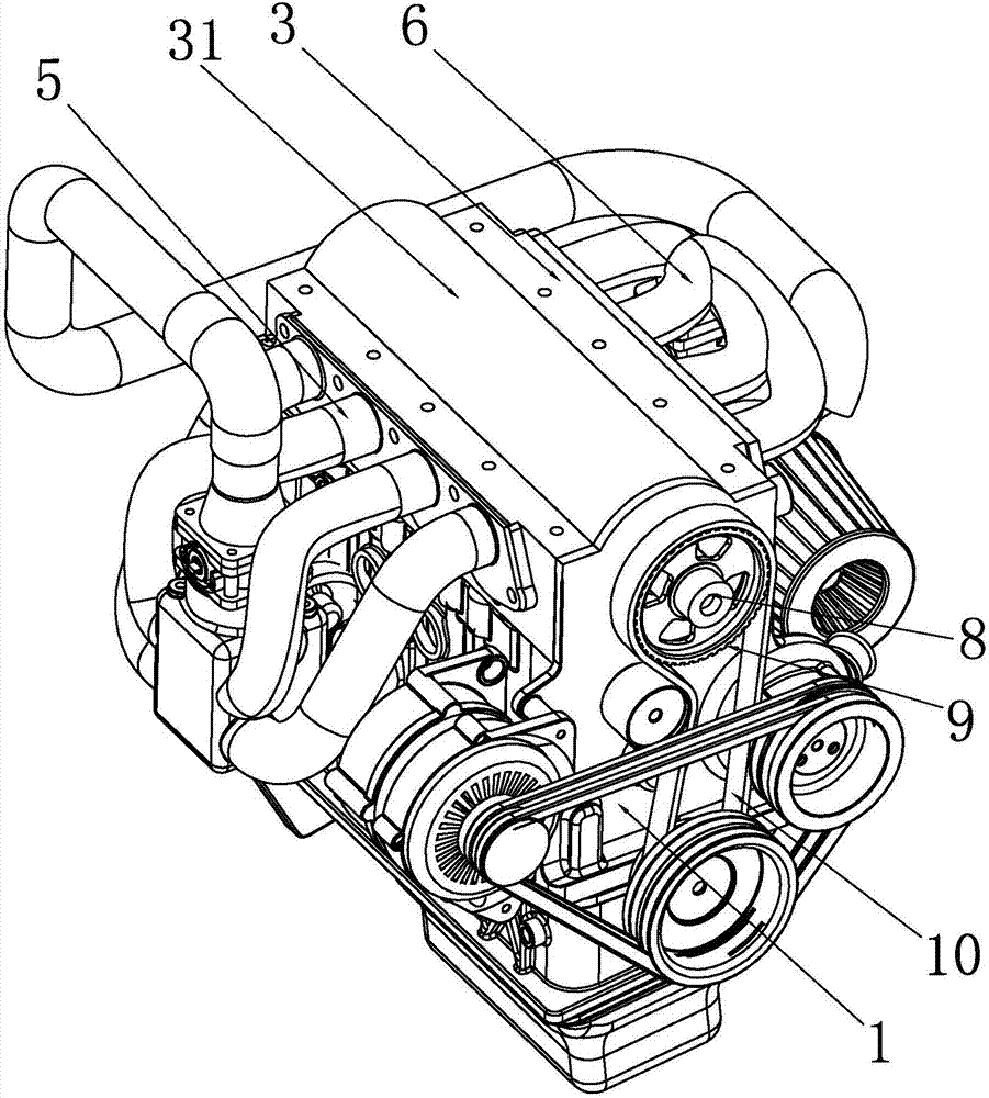
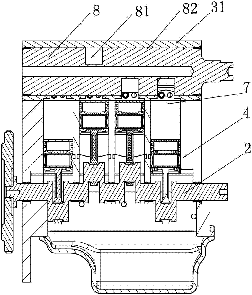
[0021] see figure 1 and figure 2 , a rotary shaft valve engine of the present invention includes a cylinder block 1, a crankshaft 2 and a cylinder head assembly 3, the cylinder block 1 is provided with four cylinders 4 arranged in a row, and the cylinder head assembly 3 includes The gas distribution mechanism, the cylinder head 31 and the gas valve chamber located inside the cylinder head 31, the gas distribution mechanism includes four air inlets 5 arranged in a row and four air inlets 5 arranged in a row communicating with the left and right ends of the valve chamber respectively. The exhaust passage 6, the lower end of the valve chamber communicates with the combustion chambers of the four cylinders 4 through four air inlets 7 respectively.

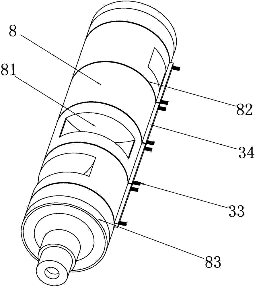
[0022] see further image 3 The valve shaft 8 that can close the valve chamber is rotated in the valve chamber, and the valve shaft 8 is correspondingly provided with four mutually misaligned ventilation grooves 81 along the axial d...


PUM


Abstract

The invention discloses a rotary shaft type gas valve engine. The rotary shaft type gas valve engine comprises a gas cylinder body, a crankshaft and a gas cylinder cover assembly, wherein the gas cylinder cover assembly comprises a gas distributing mechanism, a gas cylinder cover and a gas valve chamber positioned inside the gas cylinder cover; the gas distributing mechanism comprises four gas inlet paths which are arranged into one row and four gas outlet paths which are arranged into one row, and the gas inlet paths and the gas outlet paths separately communicate with the left end and the right end of a vent valve; the lower end of the gas valve chamber separately communicates with combustion chambers of four gas cylinders through four gas inlets; a gas valve shaft capable of sealing the gas valve chamber is rotatably arranged in the gas valve chamber; rotation speed of the crankshaft is twice that of the gas valve shaft; and four vent slots which are staggered with one another are correspondingly formed in the gas valve shaft axially. According to the rotary shaft type gas valve engine disclosed by the invention, a gas valve group is simplified into one gas valve shaft for controlling gas valves to open and close, and the gas valve shaft controls gas introduction and gas exhaustion, so that reciprocating inertial force brought to a cam shaft is reduced as the transmission way does not need the cam shaft, the structure is greatly simplified, and vibration noises of the gas cylinder cover are reduced.

Description

technical field [0001] The invention relates to the field of automobile engines, in particular to a rotary shaft type valve engine. Background technique [0002] At present, the four-stroke automobile engine generally adopts a valve-type gas distribution cylinder head assembly. The gas distribution mechanism in the cylinder head assembly is generally an upper-mounted type. The whole mechanism has many moving parts and a long transmission chain. The cylinder head assembly is the engine gas distribution mechanism. The body combined with the cylinder head. [0003] The cylinder head is a part of the combustion chamber, and its operating conditions are relatively harsh, because it is directly in contact with the burning oil and gas, and is subjected to high temperature and high pressure after combustion. The cylinder head of an automobile engine is mostly integral. In order to ensure the sealing condition, the bolts on the cylinder head must also require a large pre-tightening ...

Claims


Application Information

Patent Timeline
Patent Type & Authority Applications(China)
IPC IPC(8): F02B75/40F02F1/24F02F1/42
CPCF02B75/40F02F1/24F02F1/42
Inventor 邓宝清邓孟琦贾禹川耿静泽杨卓高曾发王闯梁志艺谢伟豪张汝斌邓振宇孙功锐
Owner ZHUHAI COLLEGE OF JILIN UNIV
Why Eureka
Try Eureka