
Linear compressor and refrigerant preheating method

A compressor and linear technology, applied in the field of compressors, can solve the problems of valve plate deformation, low safety and reliability, and easy damage to the exhaust valve plate, so as to avoid liquid shock and improve safety and reliability.

Active Publication Date: 2019-10-25
QINGDAO HAIER SMART TECH R & D CO LTD
View PDF4 Cites 0 Cited by
  • Summary
  • Abstract
  • Description
  • Claims
  • Application Information

AI Technical Summary

Problems solved by technology

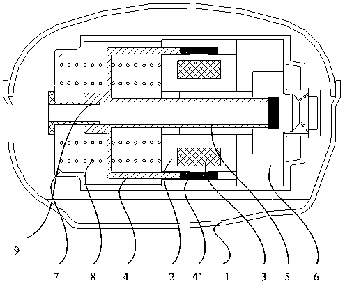
However, in actual use, when the linear compressor starts or operates at a lower ambient temperature, the low-temperature liquid refrigerant will enter the cylinder 6 from the suction tube 9, causing abnormal impact, that is, liquid hammer phenomenon.
Liquid hammer is easy to damage the exhaust valve plate of the cylinder, causing deformation and rupture of the valve plate, resulting in low safety and reliability of the linear compressor in the prior art

Method used


Image

  • Linear compressor and refrigerant preheating method
  • Linear compressor and refrigerant preheating method
  • Linear compressor and refrigerant preheating method

Examples


Embodiment Construction

[0021] In order to make the purpose, technical solutions and advantages of the embodiments of the present invention clearer, the technical solutions in the embodiments of the present invention will be clearly and completely described below in conjunction with the drawings in the embodiments of the present invention. Obviously, the described embodiments It is a part of embodiments of the present invention, but not all embodiments. Based on the embodiments of the present invention, all other embodiments obtained by persons of ordinary skill in the art without making creative efforts belong to the protection scope of the present invention.

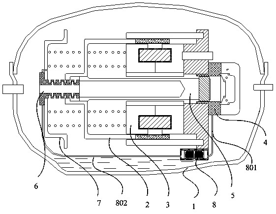
[0022] Such as figure 2 As shown, the linear compressor of this embodiment includes a casing 1, and a mover 2, a stator 3, a cylinder 4, a piston 5, a spring pressure plate 7, an air suction cylinder 6 and an oil pump 8 arranged in the casing 1. Lubricating oil is stored at the bottom of the casing 1, and the oil pump 8 is connected with a ...


PUM


Abstract

The invention provides a linear compressor and a refrigerant preheating method. The linear compressor comprises a shell and further comprises a stator, a rotor, an air cylinder, a piston, a spring pressing plate, an air suction barrel and an oil pump which are arranged in the shell, lubricating oil is stored in the bottom of the shell, a main oil supply pipe and a preheating oil supply pipe are connected to the oil pump, the main oil supply pipe is used for feeding the lubricating oil to the air cylinder, and the preheating oil supply pipe is used for feeding the lubricating oil to the air suction barrel. Safety and reliability of the linear compressor are improved.

Description

technical field [0001] The invention relates to a compressor, in particular to a linear compressor and a refrigerant preheating method. Background technique [0002] At present, there are two types of compressors used in refrigeration equipment: rotary and linear, such as figure 1 As shown, the linear compressor in the prior art usually includes a casing 1, a stator 2, a coil 3, a mover 4, a piston 5, a cylinder 6, a spring back baffle 7, a spring 71, an oil pump 8 and an air suction cylinder 9, etc. Component composition; wherein, the mover 4 is provided with a magnet 41, the magnet 41 is inserted in the magnetic field space formed by the stator 2, a coil 3 is placed in the stator 2, one end of the piston 5 is connected to the mover 4, and the other end of the piston 5 Inserted in the inner cavity of the cylinder 6, the suction tube 9 is arranged on the spring back baffle 7, and the piston 5 will suck gaseous refrigerant through the suction tube 9 during the reciprocating ...

Claims


Application Information

Patent Timeline
Patent Type & Authority Patents(China)
IPC IPC(8): F04B35/04F04B39/06F04B39/00F16N13/02
CPCF04B35/04F04B39/0027F04B39/06F16N13/02
Inventor 李孟成李衡国闫赛娜宋斌吴远刚高山许升
Owner QINGDAO HAIER SMART TECH R & D CO LTD
Learn More