Magnetic drive peak force modulated atomic force microscope and multi-parameter synchronous measurement method thereof
An atomic force microscope and peak force technology, used in measurement devices, scanning probe microscopy, instruments, etc., can solve the problems of limited probe drive frequency range, affecting measurement accuracy, and disturbing probe cantilever movement, etc. Practical value, improving signal-to-noise ratio, and the effect of high signal-to-noise ratio
- Summary
- Abstract
- Description
- Claims
- Application Information
AI Technical Summary
Problems solved by technology
Method used
Image
Examples
specific Embodiment approach 1
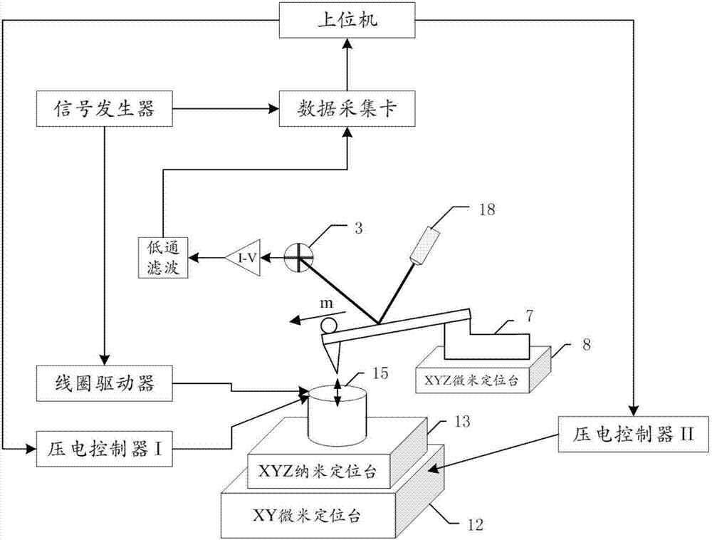
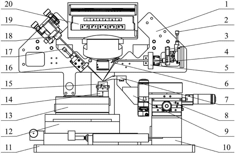
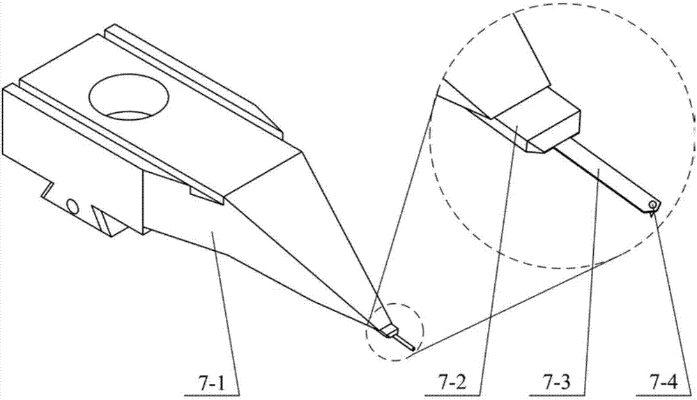
[0016] Specific implementation mode one: combine Figure 1 to Figure 4 Describe this embodiment, the magnetic drive peak force modulation atomic force microscope described in this embodiment, its probe is equipped with a coil, the frequency of the current in the coil is lower than the first-order resonance frequency of the probe, the microcantilever of the probe is connected There is a magnetic substance whose magnetization direction is along the length direction of the probe ( figure 1 The direction of the arrow at the tip of the middle probe hand) or contain components along the length of the probe.
[0017] Such as Figure 1 to Figure 3 As shown, this embodiment improves the driving method of the probe on the basis of the traditional atomic force microscope. By applying a periodic current with a certain amplitude and frequency to the driving coil to generate a periodically changing magnetic field, the The probe cantilever with a magnetic substance fixed at the end inside ...
specific Embodiment approach 2
[0018] Embodiment 2: This embodiment is a multi-parameter synchronous measurement method using the magnetic drive peak force modulation atomic force microscope described in Embodiment 1. The method is: using a periodically changing magnetic field to drive the probe at a level below its first order Vibrating below the resonance frequency, the signal controlling the relative position of the sample and the probe is the maximum indentation force of the probe tip on the sample.
specific Embodiment approach 3
[0019] Specific implementation mode three: combination Figure 5 Describe this implementation mode. This implementation mode is a further limitation of the method described in Embodiment 2. In this implementation mode, the specific steps of the method are:
[0020] Step 1. Obtain the PSD (four-quadrant semiconductor optical displacement measurement device) voltage curve U of the free-state vibration of the probe when the probe is close to the sample free ,Such as Figure 5 as shown in (a);
[0021] Step 2: Start the measurement and obtain the PSD voltage curve U of the needle tip position when the probe intermittently touches the sample inden ,Such as Figure 5 as shown in (b);
[0022] Step 3, from the voltage curve U free and the voltage curve U inden Obtain the voltage curve U of the probe force Force ;
[0023] Among them, U Force =U inden -U free
[0024] Step 4. Obtain the displacement z of the probe tip during the measurement according to the above curves i...
PUM
 Abstract
Description
Claims
Application Information
 - R&D
- Intellectual Property
- Life Sciences
- Materials
- Tech Scout
- Unparalleled Data Quality
- Higher Quality Content
- 60% Fewer Hallucinations
Browse by: Latest US Patents, China's latest patents, Technical Efficacy Thesaurus, Application Domain, Technology Topic, Popular Technical Reports.
© 2025 PatSnap. All rights reserved.Legal|Privacy policy|Modern Slavery Act Transparency Statement|Sitemap|About US| Contact US: help@patsnap.com


