Method for compensating polarization mode dispersion, polarization mode dispersion compensator and optical fiber communication system

a technology of polarization mode and compensator, which is applied in the direction of fiber transmission, distortion/dispersion elimination, instruments, etc., can solve the problems of optical communication not being realized under good conditions, increasing bit error rate, and degrading optical signals, so as to achieve more effective and efficient performance, large signal/noise ratio (s/n ratio) of optical signals, and reduce the total noise generated by amplifiers

Active Publication Date: 2005-09-20
RAKUTEN GRP INC
View PDF2 Cites 4 Cited by
  • Summary
  • Abstract
  • Description
  • Claims
  • Application Information

AI Technical Summary

Benefits of technology

[0015]If a plurality of polarization mode dispersion compensators are employed, the above-mentioned polarization mode dispersion compensating process can be performed in multistage. In this case, the compensation for the polarization mode dispersion can be performed more effectively and efficiently. Therefore, the optical communication can be realized under good condition because the optical signal can not be almost degraded due to the effective and efficient polarization mode dispersion compensation.
[0016]Moreover, in the polarization mode dispersion compensating method of the present invention, it is desired that the output of the optical signal is amplified by means of an amplifier after the polarization mode dispersion compensator. In this case, the signal loss caused by the polarizer in the compensator can be compensated in a distributed manner, and the total noise generated by the amplifiers can be decreased, so that large signal / noise ratio (S / N ratio) of the optical signal can be maintained even when the polarization mode dispersion compensators are used.

Problems solved by technology

In high speed optical communication fiber system of 10 G bits / sec and over, the polarization mode dispersion becomes conspicuous as the communication path is elongated, so that the wave distortion of an optical signal under communication also becomes large to degrade the optical signal and thus, increase the bit error rate.
As a result, the optical communication can not be realized under good condition.
In the feedback control, however, a complicated circuit is required to extract and select the monitoring signal, resulting in the complication of the total structure of the compensator.
Moreover, since it is required that two or over parameters are controlled, the algorithm becomes complicated, so that the speed of response is lowered.

Method used


Image

  • Method for compensating polarization mode dispersion, polarization mode dispersion compensator and optical fiber communication system
  • Method for compensating polarization mode dispersion, polarization mode dispersion compensator and optical fiber communication system
  • Method for compensating polarization mode dispersion, polarization mode dispersion compensator and optical fiber communication system

Examples


Embodiment Construction

[0022]This invention will be described in detail with reference to the accompanying drawings.

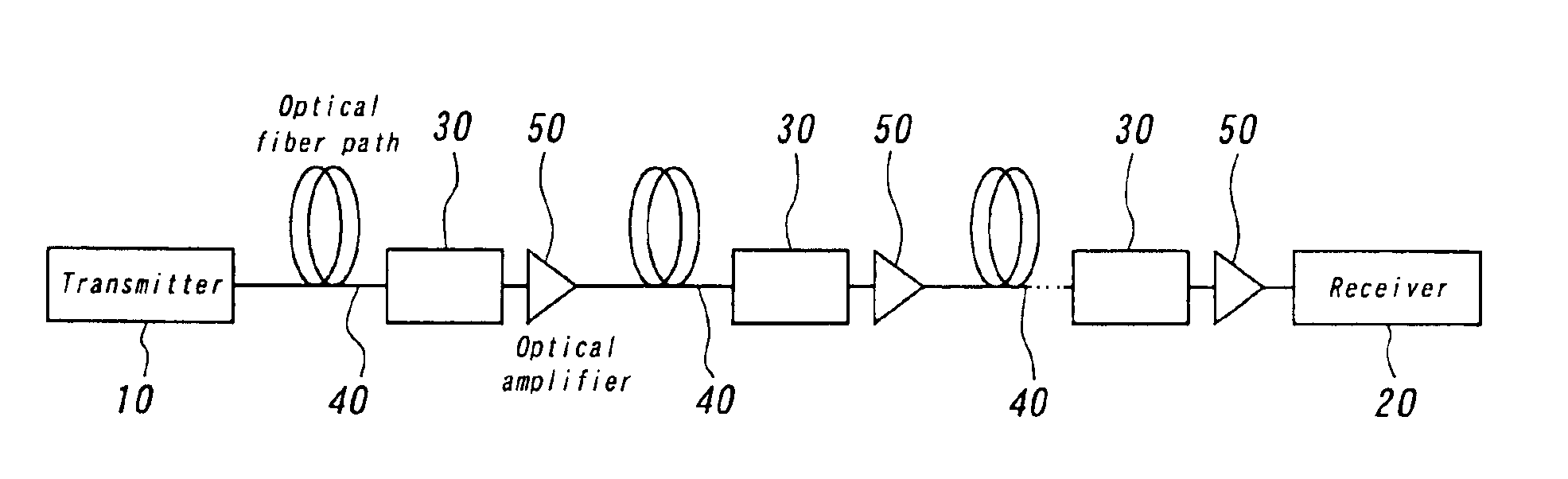
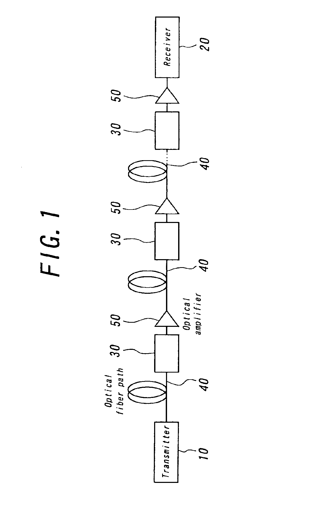
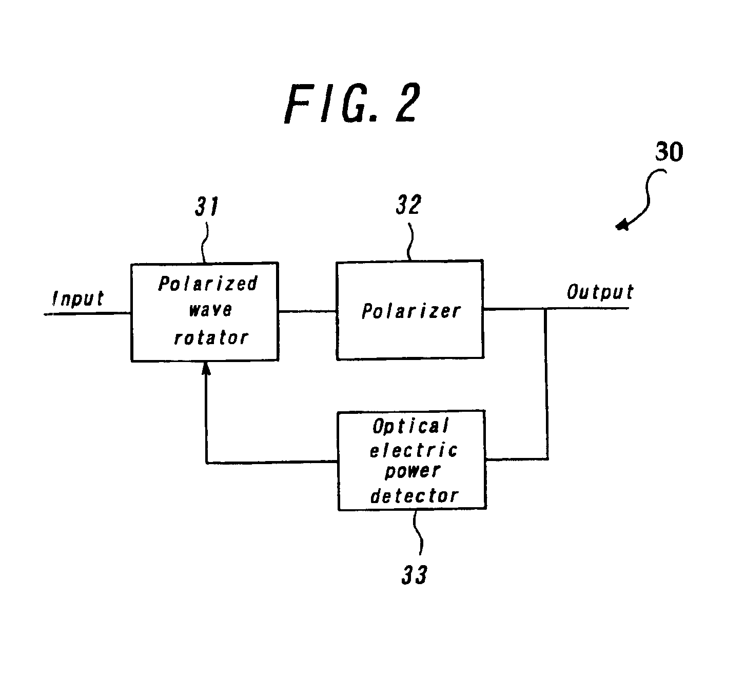
[0023]FIG. 1 is a structural view schematically illustrating an optical fiber communication system utilizing a method for compensating polarization mode dispersion according to the present invention, and FIG. 2 is a schematic view illustrating the inside of the polarization mode compensator of the optical fiber communication system illustrated in FIG. 1.

[0024]In the optical fiber communication system illustrated in FIG. 1, a transmitter 10 is provided at the transmitting end, and a receiver 20 is provided at the receiving end. Then, a plurality of polarization mode dispersion compensators 30 are arranged between the transmitter 10 and the receiver 20. The transmitter 10 and the receiver 20 are connected with each other with optical fiber paths 40 via the polarization mode dispersion compensators 30. Then, optical amplifiers 50 are provided at the respective output ends of the polarization mo...


PUM

PropertyMeasurementUnit
polarization mode dispersionaaaaaaaaaa
dispersionaaaaaaaaaa
structureaaaaaaaaaa

Abstract

An optical signal is introduced into a polarization rotator to control the optical signal so that the output of the optical signal is maximized through the rotation of a plane of polarization of the optical signal, and then, introduced into the polarizer to pass a linear polarization of the optical signal therethrough, and then, introduced into the optical electric power detector to detect the output of the optical signal.

Description

BACKGROUND OF THE INVENTION[0001]1. Field of the Invention[0002]This invention relates to a method for compensating polarization mode dispersion, a polarization mode dispersion compensator and an optical fiber communication system, which are preferably employed in high speed optical fiber communication system and the like.[0003]2. Description of the Prior Art[0004]In high speed optical communication fiber system of 10 G bits / sec and over, the polarization mode dispersion becomes conspicuous as the communication path is elongated, so that the wave distortion of an optical signal under communication also becomes large to degrade the optical signal and thus, increase the bit error rate. As a result, the optical communication can not be realized under good condition. In this point of view, in order to realize the optical communication over long communication path under good condition, it is required to compensate the polarization mode dispersion by some kind or another means. In contras...

Claims


Application Information

Patent Timeline
Patent Type & Authority Patents(United States)
IPC IPC(8): H04B10/18G02F1/01G02F1/09H04B10/07H04B10/2507H04B10/2513H04B10/2569H04B10/291
CPCH04B10/2569G02F1/0136
Inventor MATSUMOTO, MASAYUKIALZETTA, DANIELE
Owner RAKUTEN GRP INC
Why Eureka
Try Eureka