Multiparameter Simultaneous Measurement Method Using Magnetic Drive Peak Force Modulation Atomic Force Microscopy

An atomic force microscope and synchronous measurement technology, applied in measurement devices, scanning probe microscopy, instruments, etc., can solve problems such as affecting measurement accuracy, limited probe drive frequency range, and disturbing probe cantilever movement, etc. SNR, high practical value, high SNR effect

Active Publication Date: 2020-04-24
HARBIN INST OF TECH
View PDF4 Cites 0 Cited by
  • Summary
  • Abstract
  • Description
  • Claims
  • Application Information

AI Technical Summary

Problems solved by technology

[0005] The purpose of the present invention is to solve the problem that the driving frequency range of the probe is limited in the traditional driving method of the atomic force microscope based on the force-displacement curve, and the overall driving of the probe in a liquid environment will interfere with the movement of the probe cantilever and affect the measurement accuracy. , providing a magnetic drive peak force modulation atomic force microscope and multi-parameter synchronous measurement method

Method used


Image

  • Multiparameter Simultaneous Measurement Method Using Magnetic Drive Peak Force Modulation Atomic Force Microscopy
  • Multiparameter Simultaneous Measurement Method Using Magnetic Drive Peak Force Modulation Atomic Force Microscopy
  • Multiparameter Simultaneous Measurement Method Using Magnetic Drive Peak Force Modulation Atomic Force Microscopy

Examples


specific Embodiment approach 1

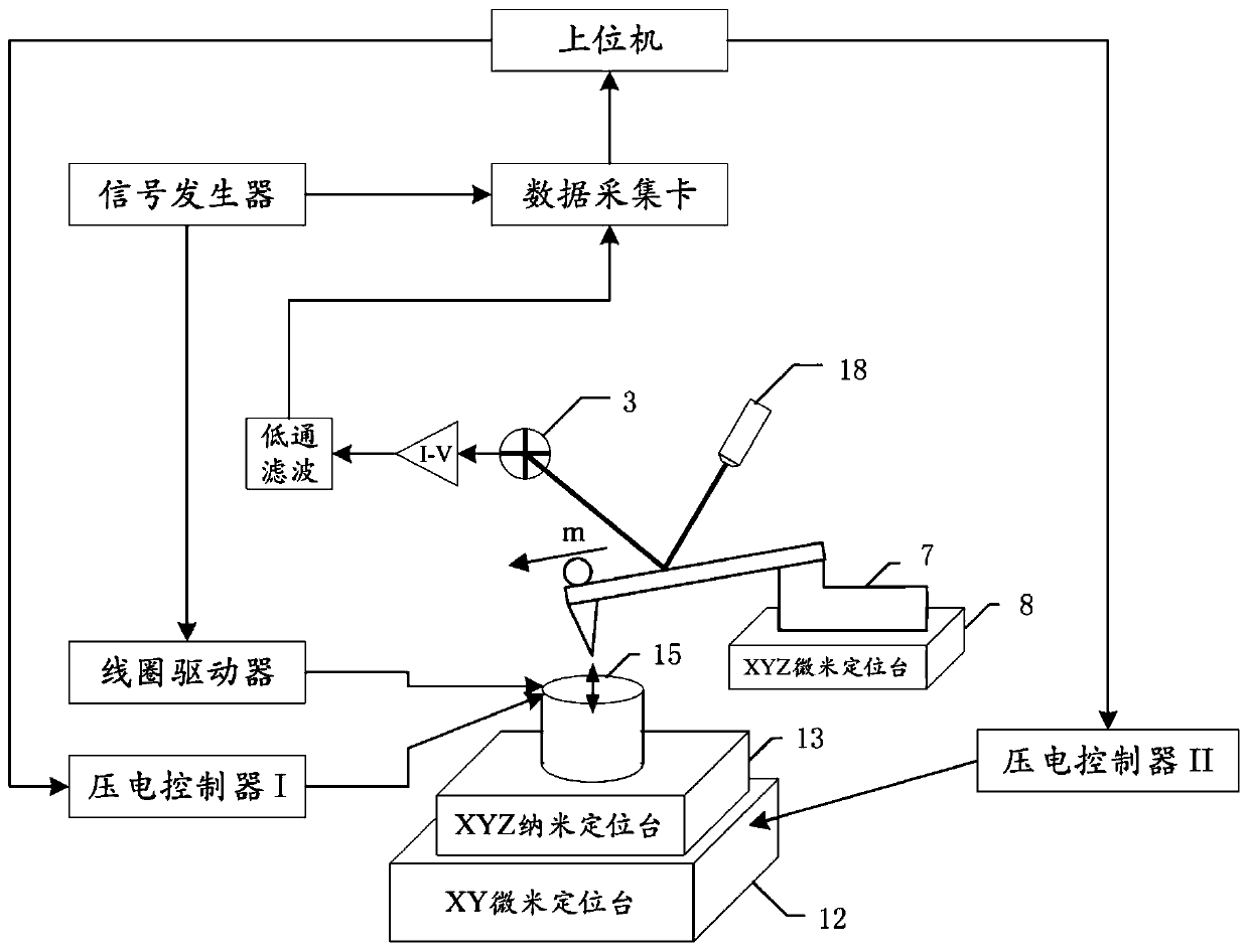
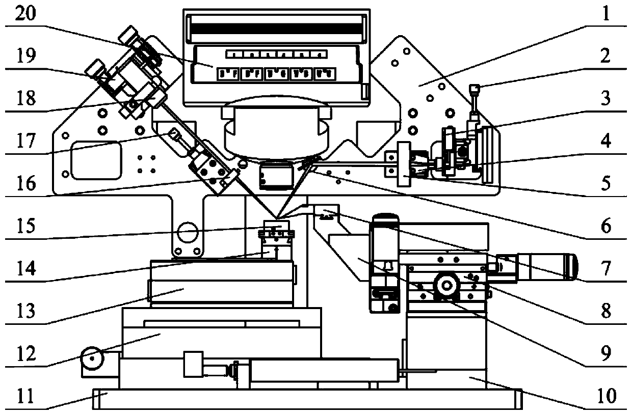
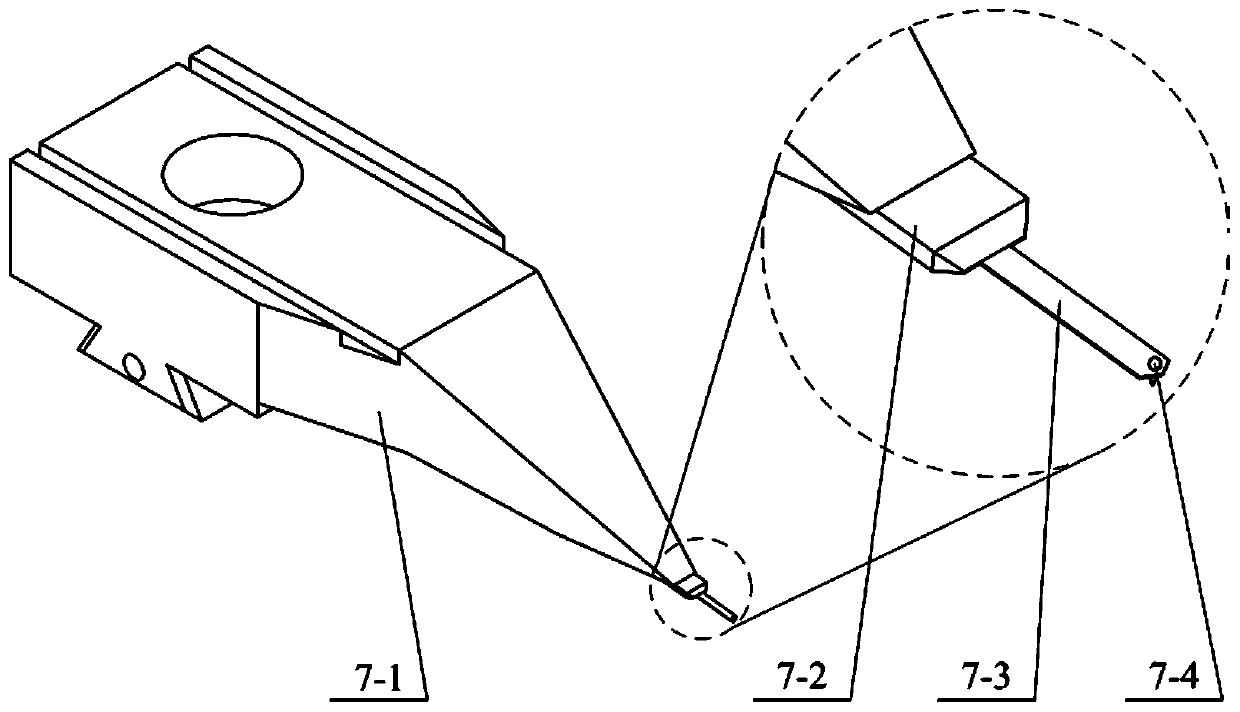
[0016] Specific implementation mode one: combine Figure 1 to Figure 4 Describe this embodiment, the magnetic drive peak force modulation atomic force microscope described in this embodiment, its probe is equipped with a coil, the frequency of the current in the coil is lower than the first-order resonance frequency of the probe, the microcantilever of the probe is connected There is a magnetic substance whose magnetization direction is along the length direction of the probe ( figure 1 The direction of the arrow at the tip of the middle probe hand) or contain components along the length of the probe.

[0017] like Figure 1 to Figure 3 As shown, this embodiment improves the driving method of the probe on the basis of the traditional atomic force microscope. By applying a periodic current with a certain amplitude and frequency to the driving coil to generate a periodically changing magnetic field, the The probe cantilever with a magnetic substance fixed at the end inside it ...

specific Embodiment approach 2

[0018] Embodiment 2: This embodiment is a multi-parameter synchronous measurement method using the magnetic drive peak force modulation atomic force microscope described in Embodiment 1. The method is: using a periodically changing magnetic field to drive the probe at a level below its first order Vibrating below the resonance frequency, the signal controlling the relative position of the sample and the probe is the maximum indentation force of the probe tip on the sample.

specific Embodiment approach 3

[0019] Specific implementation mode three: combination Figure 5 Describe this implementation mode. This implementation mode is a further limitation of the method described in Embodiment 2. In this implementation mode, the specific steps of the method are:

[0020] Step 1. Obtain the PSD (four-quadrant semiconductor optical displacement measurement device) voltage curve U of the free-state vibration of the probe when the probe is close to the sample free ,like Figure 5 as shown in (a);

[0021] Step 2: Start the measurement and obtain the PSD voltage curve U of the needle tip position when the probe intermittently touches the sample inden ,like Figure 5 as shown in (b);

[0022] Step 3, from the voltage curve U free and the voltage curve U inden Obtain the voltage curve U of the probe force Force ;

[0023] Among them, U F o rce =U inden -U free

[0024] Step 4. Obtain the displacement z of the probe tip during the measurement according to the above curves inde...


PUM


Abstract

The invention provides a magnetic drive peak force modulated atomic force microscope and a multi-parameter synchronous measurement method thereof, relates to the technology of measurement of the material surface topography and mechanical properties under the micro-nano scale, and aims at solving the problems that the driving frequency range of the probe in the conventional method based on the force-displacement curve is limited and integrally driving the probe interferes the movement of the probe cantilever and influences the measurement accuracy under the liquid environment. A coil is arranged in a sample table. The probe tip is provided with magnetic particles which are magnetized along the length direction of the probe or have the magnetized component of the direction. Firstly the PSD voltage curve U<free> of vibration of the probe in the free state is acquired, then the PSD voltage curve U<inden> of the tip position when the probe intermittently contacts the sample is acquired, the voltage curve U<Force> of the probe under stress is acquired by U<free> and U<inden>, and the force-displacement curve is acquired according to all the curves so as to acquire the mechanical properties of the material through combination of the corresponding contact mechanical model. The driving frequency range of the probe is wide and the measurement accuracy is high so as to be suitable for the research of polymer composite material or biological cells.

Description

technical field [0001] The invention relates to a measurement technique for the surface morphology and mechanical properties of materials at the micro-nano scale. Background technique [0002] Nanoscale morphology observation and characterization of physical properties of different materials are important means for studying polymer composites or biological cells. How to realize the characterization of the nanomechanical properties of samples with wide Young's modulus components in a wide measurement frequency range is the key to the study of polymer materials or living biological cells at the micro-nano scale. In the existing methods based on atomic force microscopy to measure the physical properties of materials by driving the probe deflection motion, they can be divided into two categories according to whether the probe is in a resonance state: one is to drive the probe to move around the resonance frequency, and the other is to control the probe to move around the resonan...

Claims


Application Information

Patent Timeline
Patent Type & Authority Patents(China)
IPC IPC(8): G01Q60/24G01Q60/38G01Q10/00
CPCG01Q10/00G01Q60/24G01Q60/38
Inventor 谢晖孙立宁孟祥和张号宋健民
Owner HARBIN INST OF TECH
Why Eureka
Try Eureka