Imaging system for imaging a region of interest from energy-dependent projection data

a projection data and imaging system technology, applied in the direction of instruments, material analysis using wave/particle radiation, nuclear engineering, etc., can solve the problems of time-consuming segmentation of initial images, inaccurate segmentation of computed tomography images, etc., to maximize the likelihood of the first projection data given the attenuation component images, and the deviation of the second projection data

Inactive Publication Date: 2010-04-15
KONINKLIJKE PHILIPS ELECTRONICS NV
View PDF9 Cites 5 Cited by
  • Summary
  • Abstract
  • Description
  • Claims
  • Application Information

AI Technical Summary

Benefits of technology

[0009]In an embodiment, the imaging system further comprises an attenuation component image combination unit for combining attenuation component images resulting in a combined attenuation component image. By combining attenuation component images a larger signal-to-noise ratio can be achieved.
[0010]It is further preferred that the attenuation component image generation unit is adapted for generating the attenuation component images such that deviations of the second projection data from the first projection data are reduced by generating the attenuation component images such that the likelihood of the first projection data given the attenuation component images is maximized. Since the second projection data depend on the attenuation component images, deviations of the second projection data from the first projection data can be effectively minimized by maximizing the likelihood of the attenuation component images given the first projection data, resulting in a further reduction of artifacts in the attenuation component images of the region of interest.
[0011]In a preferred embodiment, the projection data providing unit is adapted for providing energy-dependent first projection data comprising projection data values in energy windows, wherein the attenuation component image generation unit is adapted for determining for each projection data value of the first projection data in each energy window a likelihood of the first projection data value given the respective data value of the second projection data and for generating the attenuation component images such that the product of the likelihoods determined for each projection data value of the first projection data in each energy window is maximized. The use of this likelihood allows determining the attenuation component images in an uncomplicated way, wherein the artifacts in the resulting attenuation component images are further reduced.
[0012]It is further preferred that the attenuation component image generation unit is adapted for determining the likelihood of the first projection data given the attenuation component images and a noise model. Since the likelihood considers not only the first projection data, but also a noise model, the quality of the reconstructed attenuation component images will be further improved. The noise model depends on the noise present in the first projection data. Preferentially, the noise model is a Poisson model. It is further preferred that the noise model is a Poisson model, wherein the second projection data are the mean.
[0013]In a further aspect of the present invention a determination device for determining attenuation component images of a region of interest from provided energy-dependent first projection data is provided, comprising an attenuation component image generation unit for generating attenuation component images of the region of interest by generating energy-dependent second projection data using a model in which the projection data depend on attenuation component images, wherein the attenuation component image generation unit is adapted for generating the attenuation component images such that deviations of the second projection data from the first projection data are reduced.

Problems solved by technology

A segmentation of a computed tomography images is often inaccurate, in particular, if parts of an object have to be segmented which have almost the same image values leading to artifacts in the finally reconstructed image.
In addition, a segmentation of an initial image is very time consuming.

Method used


Image

  • Imaging system for imaging a region of interest from energy-dependent projection data
  • Imaging system for imaging a region of interest from energy-dependent projection data
  • Imaging system for imaging a region of interest from energy-dependent projection data

Examples


Embodiment Construction

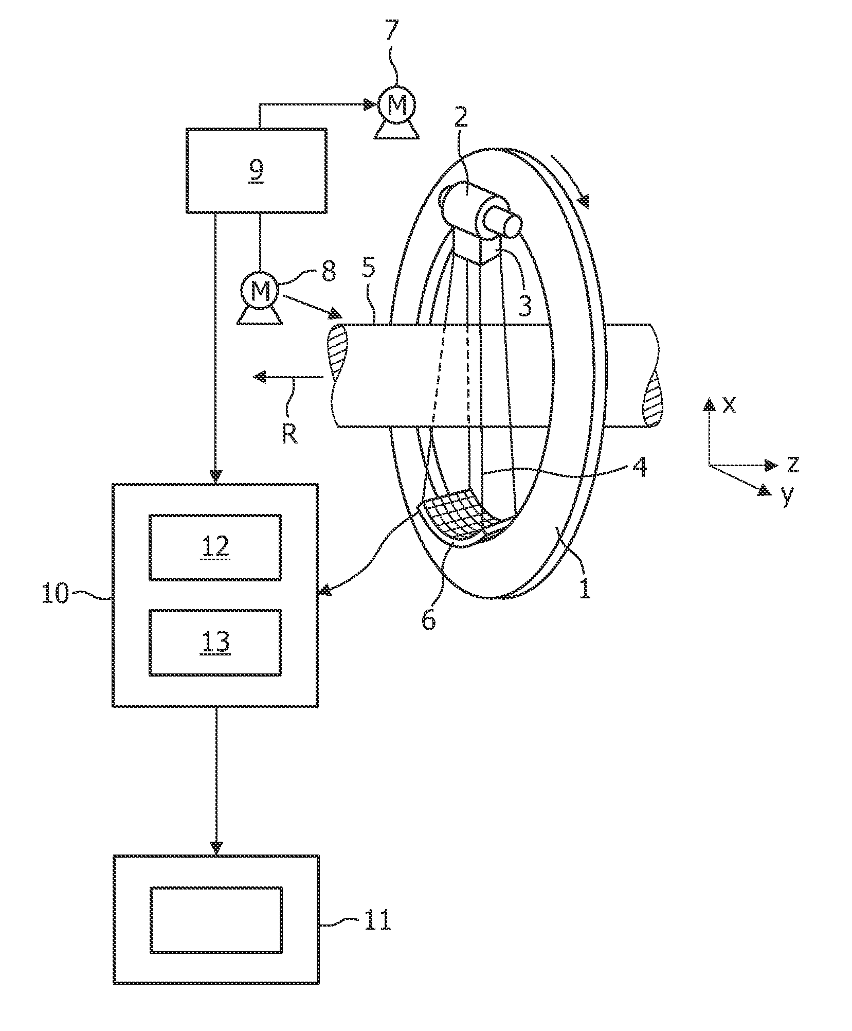
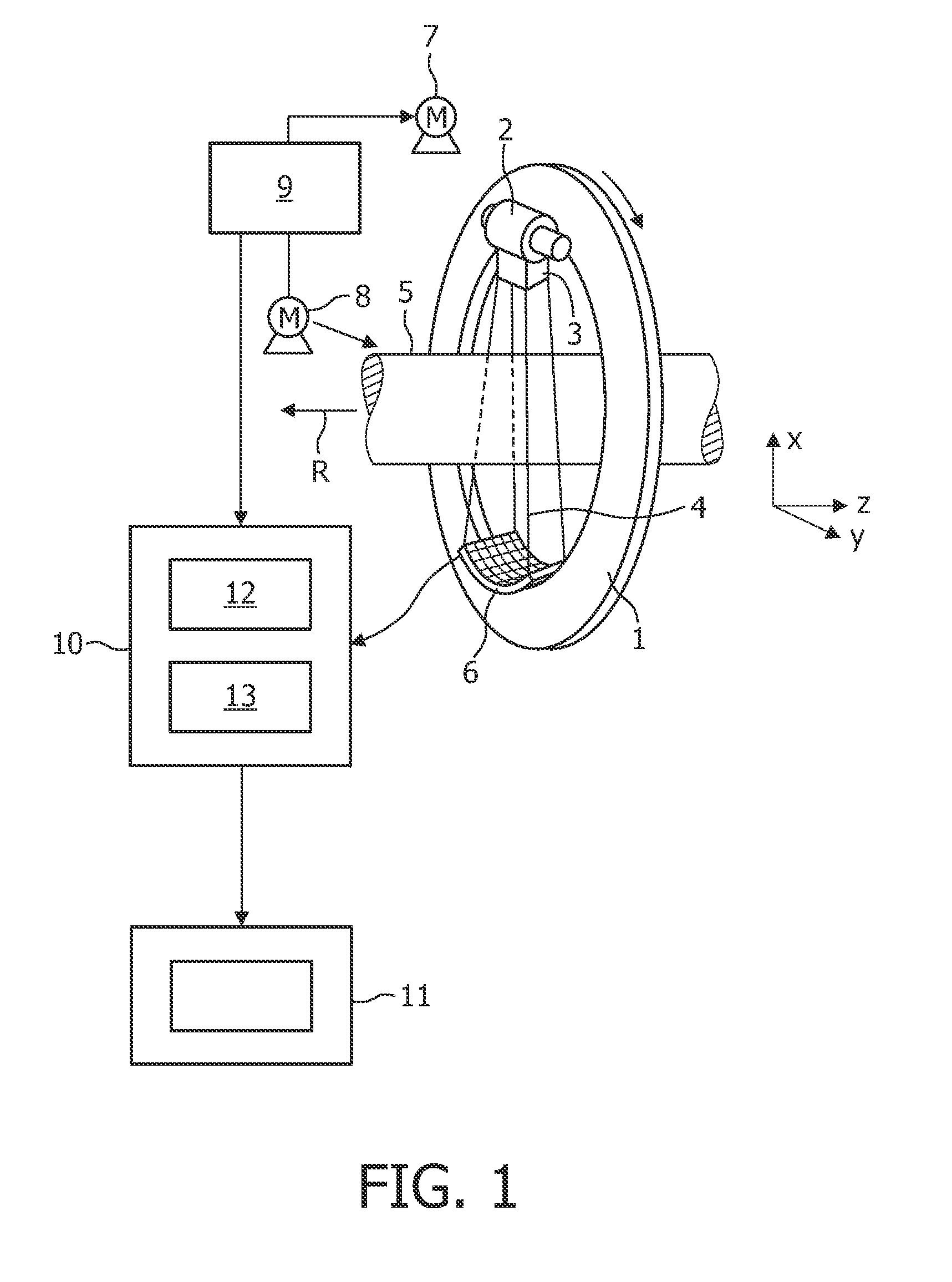
[0025]The imaging system for imaging a region of interest from energy-dependent projection data shown in FIG. 1 is, in this embodiment, a computed tomography system. The computed tomography system includes a gantry 1 which is capable of rotating around an axis of rotation R, which extends parallel to the z-direction. A radiation source 2, for example an X-ray tube, is mounted on the gantry 1. In this embodiment, the radiation source 2 emits polychromatic radiation. The radiation source 2 is provided with a collimator device 3 which forms a conical radiation beam 4 from the radiation emitted by the radiation source 2. In other embodiments, the collimator device 3 can be adapted for forming a radiation beam having another shape, for example, having a fan shape.

[0026]The radiation traverses an object (not shown), such as a patient or a technical object, in a region of interest in a cylindrical examination zone 5. After having traversed the region of interest, the radiation beam 4 is in...


PUM

PropertyMeasurementUnit
energyaaaaaaaaaa
energy-aaaaaaaaaa
computed tomographyaaaaaaaaaa

Abstract

The invention relates to an imaging system for imaging a region of interest from energy-dependent projection data, wherein the imaging system comprises a projection data providing unit (1, 2, 3, 6, 7, 8) for providing energy-dependent first projection data of the region of interest. The imaging system comprises further an attenuation component image generation unit (12) for generating attenuation component images of the region of interest by generating energy-dependent second projection data using a model in which the projection data depend on attenuation component images. The component image generation unit (12) is adapted for generating the attenuation component images such that deviations of the second projection data from the first projection data are reduced.

Description

FIELD OF THE INVENTION[0001]The invention relates to an imaging system, an imaging method and a computer program for imaging a region of interest from energy-dependent projection data.BACKGROUND OF THE INVENTION[0002]U.S. Pat. No. 6,507,633 B1 discloses a computed tomography system, which reconstructs an initial image of a region of interest from measured energy-dependent projection data. The initial image is segmented into several segments, wherein each segment represents another kind of material. For example, one segment can represent bones and another segment can represent soft tissue of a patient. A model for generating calculated energy-dependent projection data is used, which takes the different absorption distributions of the different kind of materials in the different segments into account, and deviations of the calculated energy-dependent projection data from the measured-projection data are minimized by modifying the different absorption distributions of the different kin...

Claims


Application Information

Patent Timeline
Patent Type & Authority Applications(United States)
IPC IPC(8): G01N23/04H05G1/60
CPCG06T11/006G06T2211/424G06T2211/408
Inventor PROKSA, ROLAND
Owner KONINKLIJKE PHILIPS ELECTRONICS NV
Why Eureka
Try Eureka