
Convenient mower and working method thereof

A working method and lawn mower technology, applied to harvesters, cutters, agricultural machinery and implements, etc., can solve the problems that weeds cannot be completely cleaned up, staff's arms are uncomfortable, and it takes a lot of labor and time to achieve The effect of solving the difficulty of recycling broken grass, solving the discomfort, and reducing the occupied space

Inactive Publication Date: 2017-12-12
太仓市格雷得五金有限公司
View PDF5 Cites 1 Cited by
  • Summary
  • Abstract
  • Description
  • Claims
  • Application Information

AI Technical Summary

Problems solved by technology

[0003] At present, our common machine pruning, in the pruning process, mostly during the pruning process, the pruned grass is crushed while pruning, the crushed weeds are directly sprinkled on the ground, and then the weeds sprinkled on the ground are sprayed by a special person. It takes a lot of labor and time to clean up, and many small weeds cannot be cleaned up completely. Even if some lawn mowers are equipped with a grass harvesting mechanism, the recovered weeds are too loose and take up a lot of space, which requires constant cleaning. It is very time-consuming to pour the recovered weeds to the designated location; the whole process is also very time-consuming;
[0004] At the same time, the existing lawn mowers will vibrate continuously during the working process, and the staff's arms will be tired and various discomforts will occur in the case of long-term shaking, so the existing lawn mowers still needs to be improved

Method used


Image

  • Convenient mower and working method thereof
  • Convenient mower and working method thereof
  • Convenient mower and working method thereof

Examples


Embodiment 1

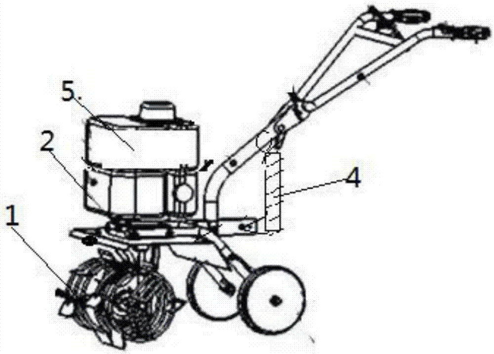
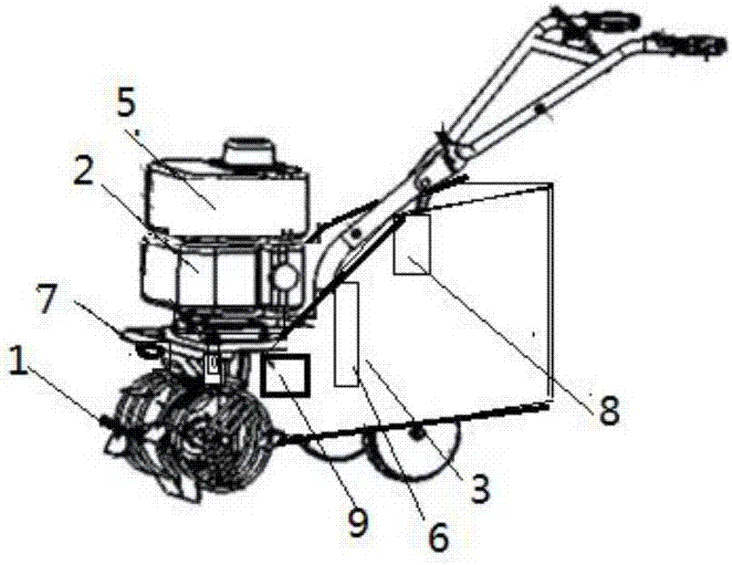
[0034] A working method of a convenient lawnmower as shown in the figure, wherein the lawnmower includes: a lawnmower body, the lawnmower body is provided with a cutting mechanism 1, a driving mechanism 2, a grass harvesting mechanism 3, a cutting mechanism Vibration mechanism 4 and control device 5, wherein, described grass collecting mechanism 3 is provided with compression device 6;

[0035] The relationship between the above components is as follows:

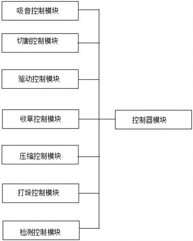
[0036] The input and output ends of the drive mechanism 2 are connected with the cutting mechanism 1 respectively, the grass collecting mechanism 3 is arranged at the rear of the cutting mechanism 1, and the shock absorbing mechanism 4 is arranged on the handrail of the mower, and the cutting mechanism 1. The driving mechanism 2, the grass collecting mechanism 3, the damping mechanism 4 and the compression device 6 are all connected to the control device 5.

[0037] In this embodiment, the compression mechanism 5 is provide...

Embodiment 2

[0045]A working method of a convenient lawnmower as shown in the figure, wherein the lawnmower includes: a lawnmower body, the lawnmower body is provided with a cutting mechanism 1, a driving mechanism 2, a grass harvesting mechanism 3, a cutting mechanism Vibration mechanism 4 and control device 5, wherein, described grass collecting mechanism 3 is provided with compression device 6;

[0046] The relationship between the above components is as follows:

[0047] The input and output ends of the drive mechanism 2 are respectively connected with the cutting mechanism 1, the grass collecting mechanism 3 is arranged at the rear of the cutting mechanism 1, and the damping mechanism 4 is arranged on the handrail of the mower, and the cutting mechanism 1. The driving mechanism 2, the grass collecting mechanism 3, the damping mechanism 4 and the compression device 6 are all connected to the control device 5.

[0048] In this embodiment, the compression mechanism 5 is provided with a ...

Embodiment 3

[0057] A working method of a convenient lawnmower as shown in the figure, wherein the lawnmower includes: a lawnmower body, the lawnmower body is provided with a cutting mechanism 1, a driving mechanism 2, a grass harvesting mechanism 3, a cutting mechanism Vibration mechanism 4, noise reduction device 9 and control device 5, wherein, described grass collecting mechanism 3 is provided with compression device 6;

[0058] The relationship between the above components is as follows:

[0059] The input and output ends of the drive mechanism 2 are respectively connected with the cutting mechanism 1, the grass collecting mechanism 3 is arranged at the rear of the cutting mechanism 1, and the damping mechanism 4 is arranged on the handrail of the mower, and the cutting mechanism 1. The driving mechanism 2, the grass collecting mechanism 3, the damping mechanism 4 and the compression device 6 are all connected to the control device 5.

[0060] In this embodiment, the compression mech...


PUM


Abstract

The invention discloses a working method of a convenient mower. The mower comprises a mower body, a cutting mechanism, a driving mechanism, a grass recovery mechanism, a damping mechanism and a control device are arranged on the mower body, a compression device is arranged in the grass recovery mechanism, an input end and an output end of the driving mechanism are connected with the cutting mechanism, the grass recovery mechanism is arranged in the rear of the cutting mechanism, the damping mechanism is arranged on an armrest of the mower, and the cutting mechanism, the driving mechanism, the grass recovery mechanism, the damping mechanism and the compression device are connected with the control device. Cut grasses are recovered by the grass recovery mechanism, the problem of difficulty in broken grass recovery is effectively solved, the recovered grasses are compressed by the compression device, space occupied by the grasses is reduced, grass pouring time is shortened, working efficiency is improved, at the same time, vibratory sensation in the working process of the mower is reduced by the damping mechanism, and the problem of discomfort caused by vibration of a current mower is effectively solved.

Description

technical field [0001] The invention belongs to the technical field of environmental protection, and in particular relates to a convenient lawn mower and a working method thereof. Background technique [0002] With the rapid development of social economy, people's living standards and quality of life are constantly improving, and whether it is production or life, people's pace is constantly accelerating. In the past, most of the weeds on green land or cultivated land It is through manual weeding, especially lawn lamps, which require manual trimming. However, with the development of the economy, most of the current lawn trimming has achieved machine trimming. [0003] At present, our common machine pruning, in the pruning process, mostly during the pruning process, the pruned grass is crushed while pruning, the crushed weeds are directly sprinkled on the ground, and then the weeds sprinkled on the ground are sprayed by a special person. It takes a lot of labor and time to cl...

Claims


Application Information

Patent Timeline
IPC IPC(8): A01D34/00A01D43/063
CPCA01D34/00A01D34/006A01D43/0633
Inventor 黄晓雷
Owner 太仓市格雷得五金有限公司
Learn More