Punching device for LED lamp production

A technology for LED lamps and punching devices, which is applied to manufacturing tools, boring/drilling, drilling/drilling equipment, etc., can solve problems such as difficulty in ensuring parts processing accuracy, increasing human resource allocation, and wasting labor input. , to achieve the effect of ensuring stability, reducing equipment vibration and increasing safety

Inactive Publication Date: 2017-12-12
芜湖晶鑫光电照明有限公司
View PDF3 Cites 10 Cited by
  • Summary
  • Abstract
  • Description
  • Claims
  • Application Information

AI Technical Summary

Problems solved by technology

In the production process of lamps, it is often necessary to use a punching device to punch holes in the shell of the lamp. However, the conventional punching process often requires two devices to achieve the purpose, which not only reduces the production efficiency, but also when it is necessary to When a workpiece is drilled and tapped at different positions at the same time, it still has the problem of inaccurate positioning, which makes it difficult to ensure the machining accuracy of the parts, the machining efficiency is also extremely low and the allocation of human resources is increased. The existing drilling devices are all Manually control the opening and closing, which wastes labor input, and the degree of automation is low, which cannot meet the needs of lamp drilling processing.

Method used


Image

  • Punching device for LED lamp production
  • Punching device for LED lamp production
  • Punching device for LED lamp production

Examples


Embodiment Construction

[0018] The technical solutions in the embodiments of the present invention will be clearly and completely described below in conjunction with the accompanying drawings in the embodiments of the present invention. Obviously, the described embodiments are only a part of the embodiments of the present invention, rather than all the embodiments. Based on the embodiments of the present invention, all other embodiments obtained by those of ordinary skill in the art without creative work shall fall within the protection scope of the present invention.

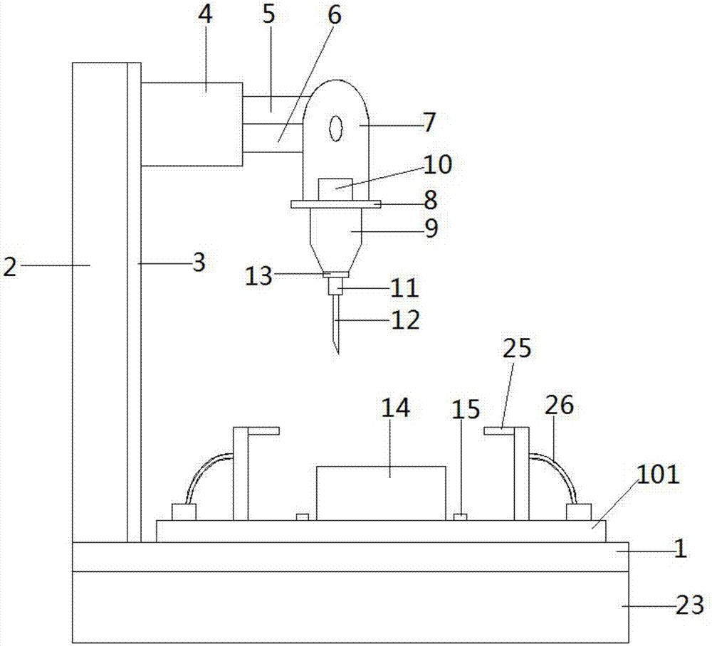
[0019] See Figure 1~3 In the embodiment of the present invention, a punching device for the production of LED lamps includes a base 1, a punch support arm 2 is fixedly connected to the upper left end of the base 1, and one side of the punch support arm 2 is provided Lifting groove 3, one side of the lifting groove 3 is provided with a first telescopic arm 4, one side of the first telescopic arm 4 is provided with a second telescopic arm...


PUM


Abstract

The invention discloses a punching device for LED lamp production. The punching device comprises a device base. A punching machine supporting arm is fixedly connected to the left end of the upper side of the device base, and a lifting groove is formed in one side of the punching machine supporting arm; a first telescopic arm is arranged on one side of the lifting groove, and a second telescopic arm is arranged on one side of the first telescopic arm; one side of the second telescopic arm is connected with a movable shaft, and the lower side of the movable shaft is provided with a punching machine bearing seat; a damper is arranged on the lower side of the device base and comprises an upper shell and a lower shell, and a separation plate is arranged between the upper shell and the lower shell; and spring assemblies are arranged on the upper end surface and the lower end surface of the separation plate correspondingly. According to the punching device for LED lamp production, the automation degree is high, use and operation are convenient, a buffer cushion is arranged on the inner side of a static chuck to protect the integrity of a workpiece, chipping blowing devices are arranged on the two sides of a working table, chippings generated through punching can be cleared in time, the punching efficiency is improved, damping can be effectively achieved, the stability is high, and the punching accuracy is high.

Description

Technical field [0001] The invention relates to the technical field of LED lamp production, in particular to a punching device for LED lamp production. Background technique [0002] Lamps and lanterns refer to appliances that can transmit light, distribute and change the light distribution of the light source, including all parts and components needed to fix and protect the light source except the light source, as well as the wiring accessories necessary for connection with the power source. In the production process of lamps and lanterns, it is necessary to often use a punching device to punch the lamp shell, etc. However, the conventional punching processing often requires two equipment to achieve the purpose, which not only reduces the production efficiency, but also When a workpiece is punched and tapped at different positions at the same time, it still has the problem of insufficient positioning, which makes it difficult to ensure the machining accuracy of the parts, the mac...

Claims


Application Information

Patent Timeline
Patent Type & Authority Applications(China)
IPC IPC(8): B23B39/10B23Q1/03B23Q11/00
CPCB23B39/10B23Q1/03B23Q11/005
Inventor 祖骅
Owner 芜湖晶鑫光电照明有限公司
Why Eureka
Try Eureka