
Water flow impacting system of ship ballast tank

A water impact and ballast tank technology, applied in the field of ships, can solve the problems of costing a lot of manpower, material resources, time, etc., and achieve the effect of reducing the required time and reducing the time in port

Inactive Publication Date: 2017-12-12
GUANGZHOU SHIPYARD INTERNATIONAL LTD
View PDF6 Cites 1 Cited by
  • Summary
  • Abstract
  • Description
  • Claims
  • Application Information

AI Technical Summary

Problems solved by technology

[0004] The object of the present invention is to provide a water impact system in the ballast tank of a ship to solve the problem in the prior art that the sediment in the ballast water is easy to form a silt layer at the bottom of the ballast tank and it takes a lot of manpower, material resources, and resources to clean up the silt layer. a matter of time

Method used


Image

  • Water flow impacting system of ship ballast tank
  • Water flow impacting system of ship ballast tank
  • Water flow impacting system of ship ballast tank

Examples


Embodiment 1

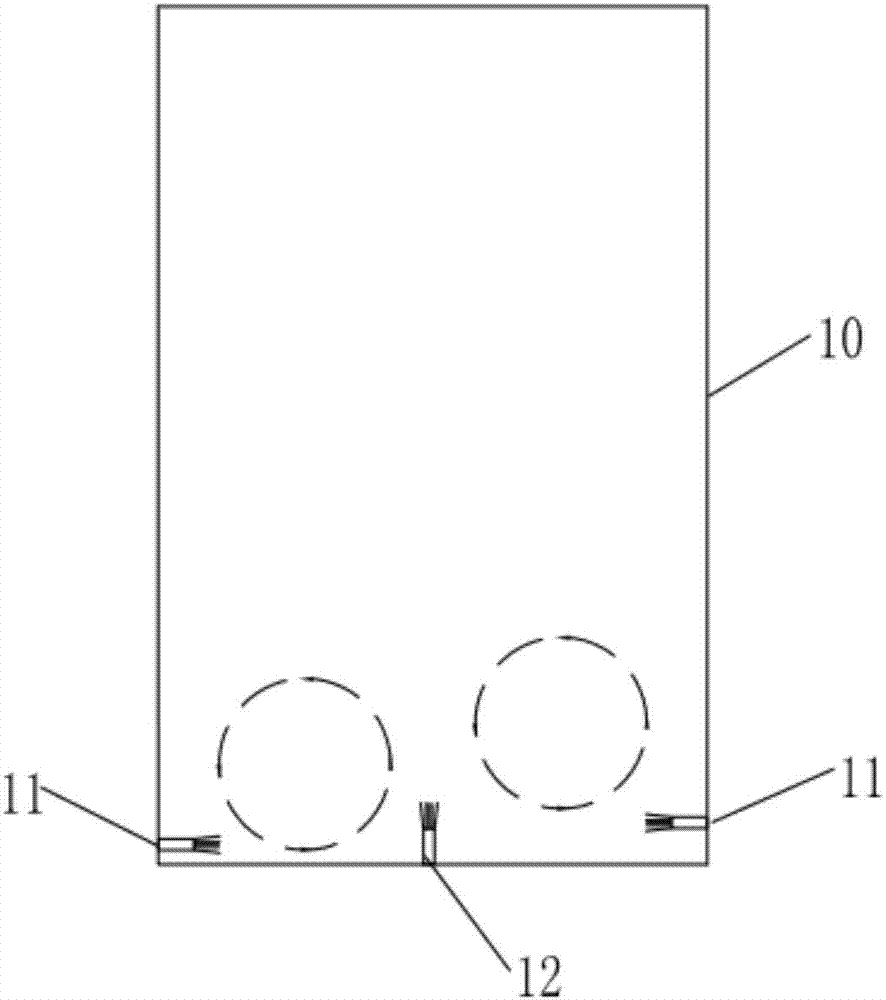
[0028] Such as figure 1 with figure 2 As shown, the present embodiment provides a ballast tank water impact system of a ship, comprising a first water nozzle group 11 composed of a plurality of first water nozzles 111, a second water nozzle group 121 composed of a plurality of second water nozzles 121. Water nozzle group 12, and water pump 13; Wherein, the first water nozzle group 11 is arranged on the sidewall of ballast tank 10, and the second water nozzle group 12 is arranged on the bilge of ballast tank 10; The water end communicates with the water source, and the water outlet end of the water pump 13 supplies water for the first water nozzle group 11 and the second water nozzle group 12 .

[0029] When the ballast water is injected into the ballast tank 10, the first water nozzle group 11 and the second water nozzle group 12 are opened, and the water flow ejected by each pair of the first water nozzle 111 and the second water nozzle 121 can be pressed against The silt ...

Embodiment 2

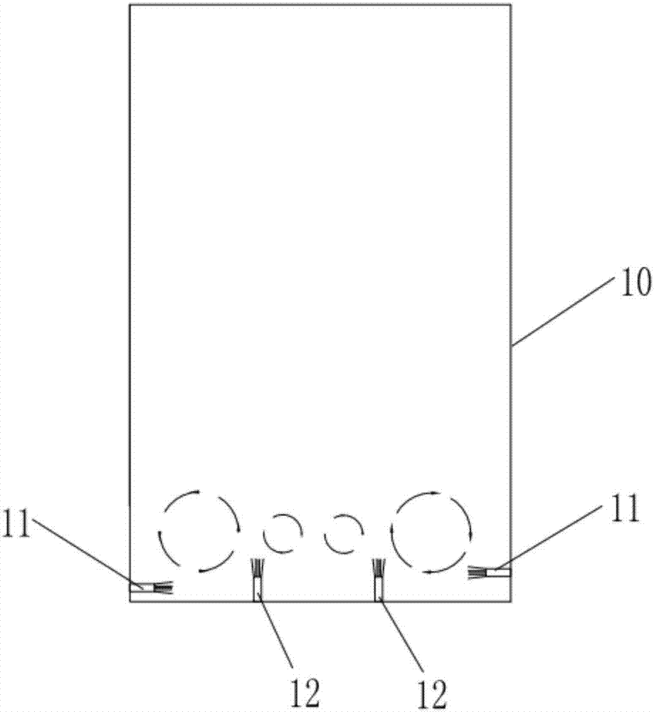
[0036] Such as Figure 3 to Figure 5 As shown, this embodiment provides a ballast tank water impact system of a ship. For the sake of brevity, only the differences between Embodiment 2 and Embodiment 1 are described. The difference is that in this embodiment, the first water nozzle The number of groups 11 is two groups, and they are respectively arranged on two opposite side walls of the ballast tank 10; The bilges of 10 are distributed at intervals and correspond to two groups of first water nozzle groups 11 respectively.

[0037] The setting form of the second water nozzle group 12 has two kinds, one such as image 3 As shown, two groups of second water nozzle groups 12 are arranged vertically with the bilge; Figure 4 As shown, the two groups of second water nozzle groups 12 are all obliquely arranged on the bottom of the ballast tank 10, and the inclination direction of one group of second water nozzle groups 12 is different from the inclination direction of the other gr...


PUM


Abstract

The invention relates to the technical field of ships, in particular to a water flow impacting system of a ship ballast tank. The water flow impacting system comprises a first water spray nozzle group composed of a plurality of first water spray nozzles, a second water spray nozzle group composed of a plurality of second water spray nozzles, and a water pump, wherein the first water spray nozzle group is arranged on the side wall of the ballast tank, and the second water spray nozzle group is arranged at the bottom of the ballast tank. The water inlet end of the water pump communicates with a water source, and the water outlet end of the water pump supplies water to the first water spray nozzle group and the second water spray nozzle group. When ballast water is injected into the ballast tank, the first water spray nozzle group and the second water spray nozzle group are opened, water flow sprayed from the first water spray nozzle group and the second water spray nozzle group can achieve water flow disturbance to sediment in ballast water, sediment can be effectively prevented from forming sludge after being settled at the bottom of the ballast tank, time required for manual removing of sludge is shortened, and time spent in harbors of ships is shortened.

Description

technical field [0001] The invention relates to the technical field of ships, in particular to a water flow impact system of a ship's ballast tank. Background technique [0002] In cargo ships transporting crude oil or containers, ballast tanks are provided to ensure the stability of the ship's hull during navigation. Usually, the ballast tank is filled with ballast water when there is no cargo such as crude oil loaded, and the ballast water is discharged when crude oil or containers need to be loaded, thereby adjusting the buoyancy of the hull to stabilize the hull. [0003] Especially for large transport ships, the amount of ballast water is even as high as 100,000 tons. In some cases (especially when the ship is in a port, estuary and other sea areas), the ballast water injected by the ship contains a large amount of sediment. After a long voyage, The sediment deposits at the bottom of the ballast tank to form a hard and thick silt layer, which requires a lot of manpower...

Claims


Application Information

Patent Timeline
Patent Type & Authority Applications(China)
IPC IPC(8): B63B39/03B63B59/00
CPCB63B39/03B63B59/00
Inventor 薛林周静
Owner GUANGZHOU SHIPYARD INTERNATIONAL LTD
Learn More