Slurry injection anchoring capsule

A bladder and grouting technology, applied in construction, sheet pile wall, infrastructure engineering, etc., can solve problems such as reducing the anchor pullout resistance, affecting the quality of the project, and preventing the external grouting pipe from being re-injected into the bottom of the bladder.

Pending Publication Date: 2017-12-12
XINXIANG JIAHUI TECH
View PDF6 Cites 0 Cited by
  • Summary
  • Abstract
  • Description
  • Claims
  • Application Information

AI Technical Summary

Problems solved by technology

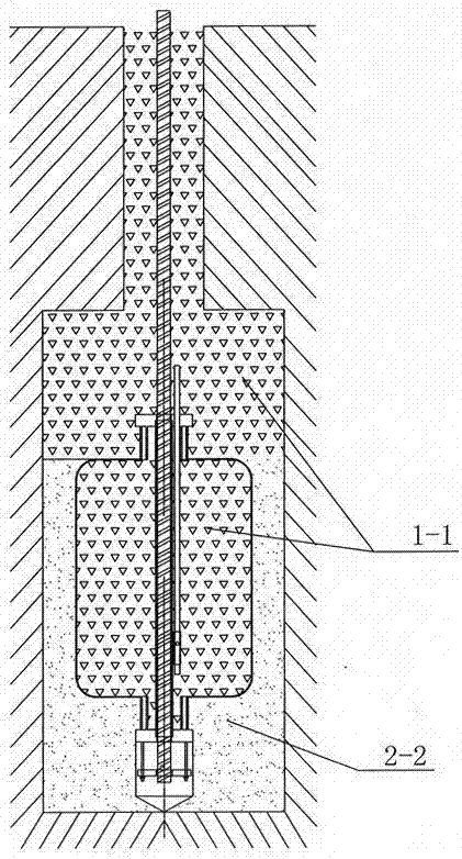
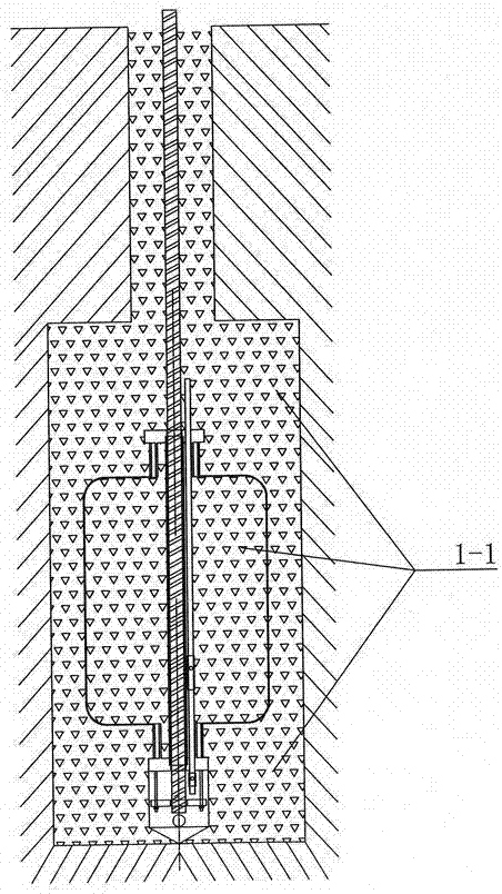
[0002] In the existing grouting and anchoring capsules, a chuck is respectively installed at both ends of a capsule, a guide tube is fixed in the bag on the two chucks, and a positioning head is installed on the lower chuck. A grouting pipe extending into the upper capsule of the positioning head is installed on the upper chuck from one side of the guide pipe, and a grouting valve is installed in the bag on the grouting pipe. The main problem of this structure Yes, after the cement slurry 1-1 fills the capsule, it expands to form an enlarged head, which prevents the external grouting pipe from re-injecting into the bottom of the capsule, and can only inject grout on the upper part of the capsule filled with cement slurry, because the capsule at this time The surrounding and lower parts are filled with clay grout 2-2, and the grout injected into the upper part of the capsule cannot effectively replace the surrounding clay grout, which affects the quality of the project and greatly reduces the pullout resistance of the anchorage

Method used


Image

  • Slurry injection anchoring capsule
  • Slurry injection anchoring capsule
  • Slurry injection anchoring capsule

Examples


Embodiment Construction

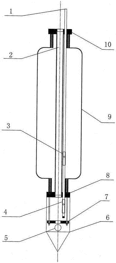
[0007] Describe embodiment in detail in conjunction with accompanying drawing, as image 3 As shown, it includes an upper chuck 10, a lower chuck 8, a positioning head guard 6 and a capsule body 9, and one or more guide tubes 2 are connected between the upper and lower chucks through the direction of the central axis of the capsule body. The outer wall of the upper positioning head guard is provided with at least one slurry discharge hole 5, and a round supporting plate 7 is installed with a suspender in the cavity of the positioning head guard, and passes through the upper chuck through the capsule body and the lower chuck to reach the positioning A grouting pipe 1 is installed in the head guard, a low-pressure grouting check valve 3 is installed in the capsule body on the grouting pipe, and a high-pressure check valve 4 is installed in the positioning head guard on the grouting pipe. The capsule body is made of reverse osmosis anti-corrosion cloth. A one-way valve is instal...


PUM


Abstract

The invention discloses a slurry injection anchoring capsule. A slurry injection pipe sequentially penetrates an upper clamping head, a capsule body and a lower clamping head from top to bottom and then extends into a positioning protection head. The part, inside the capsule body, of the slurry injection pipe is provided with a low-pressure slurry injection check valve, and the part, inside the positioning protection head, of the slurry injection pipe is provided with a high-pressure slurry injection check valve. The outer wall of the positioning protection head is provided with at least one slurry draining hole, and one-way valves are arranged on portions of the slurry draining holes. A cavity of the positioning protection head is internally provided with a round supporting plate through a suspender. One or more guiding pipes are connected in the center axis direction of the upper clamping head and the lower clamping head through the capsule body. The capsule body is made of reverse osmosis anticorrosion cloth. By means of the improvement, cement slurry can be smoothly injected into the capsule body, clay grout around the capsule body can be effectively replaced, the solidification quality of the capsule body is effectively improved, and the anti-drawing strength is improved.

Description

technical field [0001] The invention relates to construction engineering, in particular to a grouting anchor capsule used for foundation reinforcement or side slope support. Background technique [0002] In the existing grouting and anchoring capsules, a chuck is respectively installed at both ends of a capsule, a guide tube is fixed in the bag on the two chucks, and a positioning head is installed on the lower chuck. A grouting pipe extending into the upper capsule of the positioning head is installed on the upper chuck from one side of the guide pipe, and a grouting valve is installed in the bag on the grouting pipe. The main problem of this structure Yes, after the cement slurry 1-1 fills the capsule, it expands to form an enlarged head, which prevents the external grouting pipe from re-injecting into the bottom of the capsule, and can only inject grout on the upper part of the capsule filled with cement slurry, because the capsule at this time The surrounding and lower ...

Claims


Application Information

Patent Timeline
Patent Type & Authority Applications(China)
IPC IPC(8): E02D5/74
CPCE02D5/74
Inventor 贾照会张顺利
Owner XINXIANG JIAHUI TECH
Why Eureka
Try Eureka