An aerated concrete block wall structure

A technology for aerated concrete and wall structures, which is applied to walls, building components, building structures, etc., can solve the problems of damaging the overall rigidity of the structure, reducing the overall strength of the project, and worrying about the quality of the wall, so as to improve the firmness and improve the quality of the wall. Thermal insulation effect, effect of improving aesthetics

Active Publication Date: 2022-04-05
山东省建筑设计研究院有限公司
View PDF0 Cites 0 Cited by
  • Summary
  • Abstract
  • Description
  • Claims
  • Application Information

AI Technical Summary

Problems solved by technology

The quality of the existing aerated concrete block walls is worrying, often causing wall cracks, which damages the overall rigidity of the structure, reduces the overall strength of the project, and greatly reduces the stability

Method used


Image

  • An aerated concrete block wall structure
  • An aerated concrete block wall structure
  • An aerated concrete block wall structure

Examples


Embodiment 1

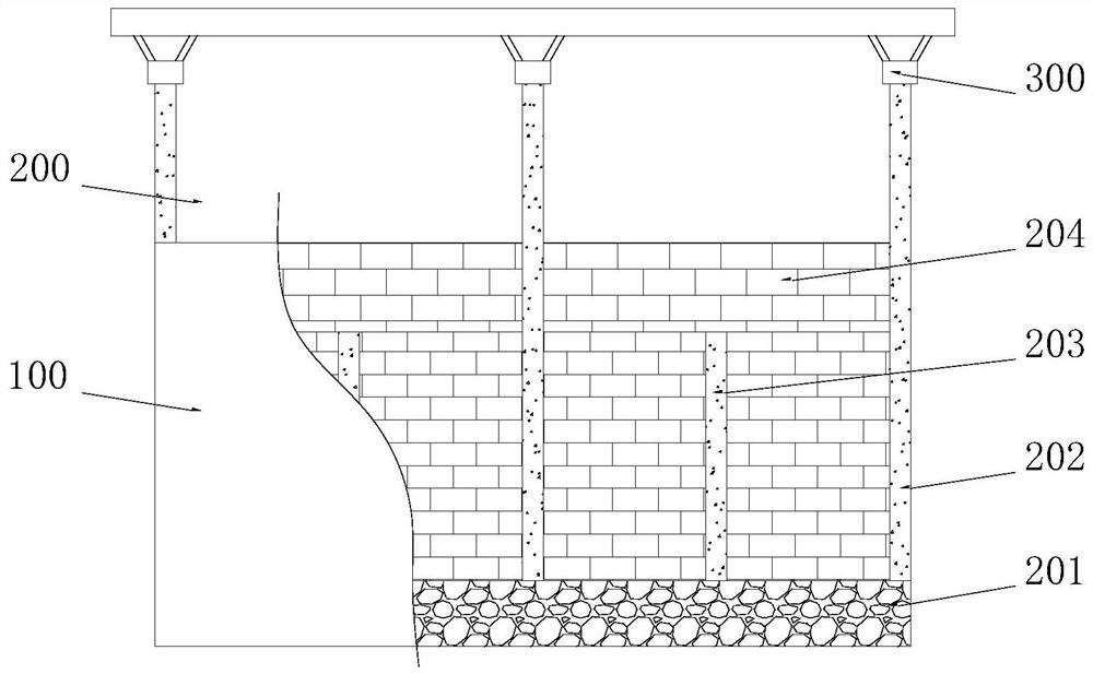
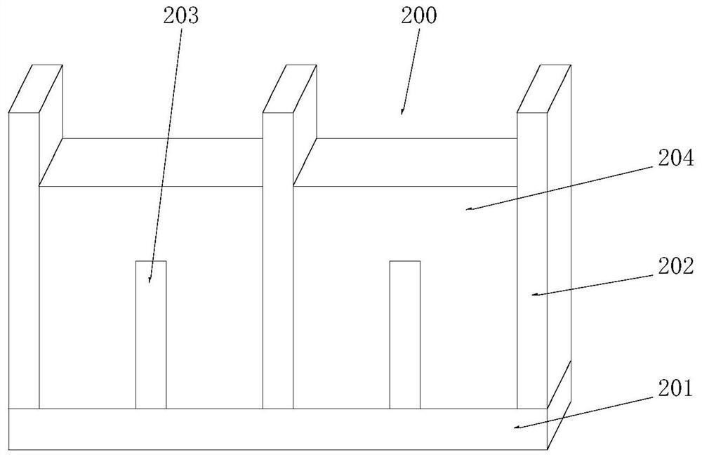
[0034] See Figure 1-2 , an aerated concrete block wall structure, comprising an inner wall 200 and two outer walls 100, the front and rear sides of the inner wall 200 are respectively provided with an outer wall 100, and the inner wall 200 includes a foundation wall 201, the foundation wall 201 is made by pouring C2O fine stone concrete, the height of the foundation wall 201 is 200 mm to 300 mm, and a steel skeleton is embedded in the foundation wall 201 to enhance the strength and stability of the foundation wall 201;

[0035] The top of the foundation wall 201 is evenly provided with several first construction columns 202 and some second construction columns 203, the height of the second construction columns 203 is less than two-thirds of the height of the second construction columns 202, the second construction The column 203 and the first structural column 202 are interlaced with each other, the second structural column 203 is made of C2O concrete, and the vertical steel ...

Embodiment 2

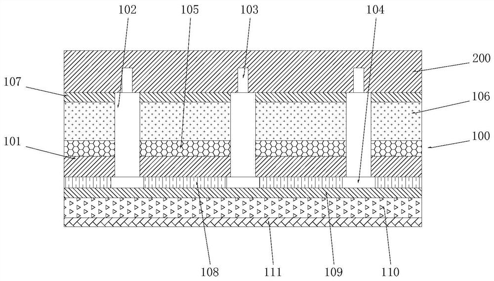
[0038] See Figure 3-4 The difference from Embodiment 1 is that the outer wall 100 includes a base plate 101, on which a number of mounting coils 102 are evenly embedded, and the front of the base plate 101 is connected to the mounting coils. 102 is flush with the positive end surface, and the mounting screw 102 is internally threaded with a fastening screw 103 that matches the inner wall 200, and the positive end of the fastening screw 103 is provided with a set that matches the base plate 101 The fastening sleeve 104, the base plate 101 can be installed on the inner wall 200 through the fastening screw 103 and the installation screw 102, and the fastening sleeve 104 can further improve the firmness of the base plate 101 installation ;The entire installation structure is very simple, which is convenient for later disassembly and maintenance;

[0039] The end of the base plate 101 close to the inner wall 200 is provided with a sound insulation layer 105 matched with the insta...

Embodiment 3

[0042] See Figure 5-6 The difference from Embodiment 1 is that the protection assembly 300 includes a protection shell 301 and several top cylinders 308 matched with the first construction column 202, the protection shell 301 is a box structure with an open bottom end, and the protection The middle part of the inner cavity of the shell 301 is provided with an inner brace 302, and the protective shell 301 and the inner brace 302 are integrally formed, and the inner brace 302 divides the inner cavity of the protective shell 301 into two working chambers 303 , all of the top tubes 308 are cylindrical structures with open bottoms, and the top of the top tubes 308 is symmetrically provided with support rods 309, and the two support rods 309 are in a figure-eight structure, and the top tubes 308 are supported by The rod 309 is fixedly connected to the bottom end of the inner support plate 302, and is set on the top of the first construction column 202 through the top tube 308, so t...


PUM


Abstract

The invention discloses an aerated concrete block wall structure, which comprises an inner wall and two outer walls, the front and rear sides of the inner wall are respectively provided with outer walls, and the inner wall includes a foundation wall , the foundation wall is embedded with a steel skeleton; the top of the foundation wall is evenly provided with a number of first construction columns and a number of second construction columns, and the first construction columns are built with the second construction columns. The matching wall body, the wall body is made of a number of aerated concrete blocks, and the aerated concrete blocks of the upper and lower floors are overlapped; the invention can greatly improve the whole device by setting the foundation wall The stability of the base, at the same time, by setting the first structural column and the second structural column as the skeleton of the wall body, and cooperating with each other to support the wall body, the strength of the inner wall can be greatly improved, and the wall can be effectively avoided. The appearance of cracks can effectively improve the service life of the entire wall structure.

Description

technical field [0001] The invention relates to the technical field of construction engineering, in particular to an aerated concrete block wall structure. Background technique [0002] Masonry engineering, also known as masonry engineering, refers to the construction of ordinary clay bricks, load-bearing clay hollow bricks, autoclaved lime sand bricks, fly ash bricks, various small and medium-sized blocks and stone materials in construction projects. . Including bricklaying, stone, blocks and lightweight wall panels and so on. Requirements for masonry materials, masonry technology, quality requirements and preventive measures for common quality problems in bricklaying, stonelaying and block-brickwork. [0003] Masonry engineering is an important sub-project in the main structural engineering, and the aerated concrete block wall is a type of masonry engineering. The quality of the aerated concrete block wall directly affects the wall structure , It also affects the constr...

Claims


Application Information

Patent Timeline
Patent Type & Authority Patents(China)
IPC IPC(8): E04B2/04E04B1/88E04B1/62
CPCE04B2/04E04B1/88E04B1/62
Inventor 文昭
Owner 山东省建筑设计研究院有限公司
Why Eureka
Try Eureka