Heat dissipation insect repellent energy-saving lamp

An energy-saving lamp and insect repellent technology, applied in the field of lighting, can solve the problems of many mosquitoes, no suitable solution, high heat generation, etc., and achieve the effect of promoting heat dissipation

Active Publication Date: 2019-04-16
邳州市鑫盛创业投资有限公司
View PDF6 Cites 0 Cited by
  • Summary
  • Abstract
  • Description
  • Claims
  • Application Information

AI Technical Summary

Problems solved by technology

[0002] Energy-saving lamps have been widely used due to their high lighting efficiency; however, during the use of energy-saving lamps, they usually face the problems of more mosquitoes and greater heat generation; because the power supply structure of energy-saving lamps contains more semiconductor components, so Affected by heat much more than incandescent lamps; there are currently no suitable solutions for these problems

Method used


Image

  • Heat dissipation insect repellent energy-saving lamp
  • Heat dissipation insect repellent energy-saving lamp
  • Heat dissipation insect repellent energy-saving lamp

Examples


Embodiment 1

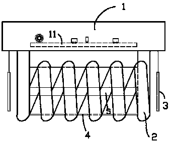
[0014] exist figure 1 In the first embodiment shown, the heat dissipation and insect repelling energy-saving lamp includes a base 1 and a lamp tube 2; a power supply structure 11 for supplying alternating current to the lamp tube is provided inside the base 1; the lamp tube 2 forms a straight spiral Tubular, placed horizontally below the base 1; and the two ends of the lamp tube 2 are connected to the base 1 from the two ends of the straight spiral tube, so that when the current is formed in the lamp tube 2, each turn of the current in the lamp tube 2 The winding direction is the same (in the traditional spiral energy-saving lamp, the lamp tubes drawn from the two poles are twisted side by side, so that the current in the adjacent turns of the spiral energy-saving lamp formed in the opposite direction, so the traditional spiral energy-saving lamp cannot forming an axial magnetic field); the two ends of the lamp tube 2 are respectively provided with a piece of decorative sheet ...

Embodiment 2

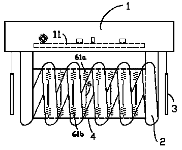
[0019] for image 3 The second embodiment shown is different from the first embodiment in that there is no iron core 5 in the heat pipe 4, but a row of thin metal circles perpendicular to the axis of the heat pipe 4 The upper and lower sides of each thin metal disc 6 are respectively connected to the heat pipe 4 through a thin spring 61a, 61b. According to the second embodiment, the axial magnetic field of the lamp tube 2 passes through each thin metal disc 6 at the same time, thereby forming an eddy current (weaker) in the same direction on each thin metal disc 6; so that each thin metal disc 6 generates an attractive force, because the eddy current is alternating, so the attractive force between the thin metal discs 6 is a wave force, so that each thin metal disc 6 vibrates laterally to promote the scale of the lateral airflow , improve the heat dissipation effect; on the other hand, the thin metal disc 6, the thin springs 61a, 61b, and the structure formed by the heat pipe...


PUM


Abstract

The invention provides a heat-dissipating and insect-repelling type energy-saving lamp. The heat-dissipating and insect-repelling type energy-saving lamp comprises a pedestal and a lamp tube, wherein a power supply structure for supplying alternating-current power to the lamp tube is arranged in the pedestal; the lamp tube is in the shape of a straight helical tube, and is transversely arranged below the pedestal; the two ends of the lamp tube are connected to the pedestal from the two ends of the straight helical tube, so that a circling direction of each turn of current in the lamp tube is the same when current is formed in the lamp tube; the two ends of the lamp tube are each separately equipped with a decorative sheet which is opposite to the end part of the lamp tube and is suspended on the pedestal; and under action of alternating magnetic fields on the surfaces of the decorative sheets, the decorative sheets can form annular current. The energy-saving lamp can achieve the insect-repelling effect without the need of extra power while improving the heat-dissipating effect.

Description

technical field [0001] The invention relates to the field of lighting, in particular to an energy-saving lamp. Background technique [0002] Energy-saving lamps have been widely used due to their high lighting efficiency; however, during the use of energy-saving lamps, they usually face the problems of more mosquitoes and greater heat generation; because the power supply structure of energy-saving lamps contains more semiconductor components, so Affected by heat far more than incandescent lamps; there are currently no suitable solutions to these problems. Contents of the invention [0003] In view of the above problems, the object of the present invention is to provide a heat-dissipating and insect-repelling energy-saving lamp. The energy-saving lamp can improve the heat dissipation effect and have the insect repelling effect at the same time without additional power. [0004] The technical solution adopted by the present invention to solve the technical problem is: the h...

Claims


Application Information

Patent Timeline
Patent Type & Authority Patents(China)
IPC IPC(8): F21S2/00F21V23/02F21V29/60
CPCF21S2/00F21V23/023F21V29/60
Inventor 李聪
Owner 邳州市鑫盛创业投资有限公司
Why Eureka
Try Eureka