Rectifier and control method thereof

A technology of rectifier and rectifier circuit, which is applied in the direction of conversion equipment without intermediate conversion to AC, irreversible AC power input conversion into DC power output, output power conversion device, etc., which can solve the problem of large output current ripple and high output voltage , complex drive and control strategies, etc., to achieve the effect of reliable and stable work and simple control

Active Publication Date: 2017-12-12
NANJING UNIV OF AERONAUTICS & ASTRONAUTICS
View PDF4 Cites 4 Cited by
  • Summary
  • Abstract
  • Description
  • Claims
  • Application Information

AI Technical Summary

Problems solved by technology

Three-phase single-switch Boost PFC circuit, in order to achieve decoupling between the three phases, three inductors are placed on the AC side, and work in the current discontinuous mode, which is characterized by simple current control, but the input and output current of the circuit The ripple is large, the filter current is high, and the output voltage is too high, which brings certain difficulties to the selection of the power tube. This circuit is generally used for output power less than 10kw and for current THD (totalharmonic distortion, total harmonic Wave distortion)) where the requirements are not strict
Although the three-phase multi-switch can control the input current with high precision and obtain excellent performance, it requires a large number of switching tubes, complex driving and control strategies, and high cost. It is suitable for high-power applications.

Method used


Image

  • Rectifier and control method thereof
  • Rectifier and control method thereof
  • Rectifier and control method thereof

Examples


Embodiment Construction

[0032] The invention will be described in further detail below in conjunction with the accompanying drawings.

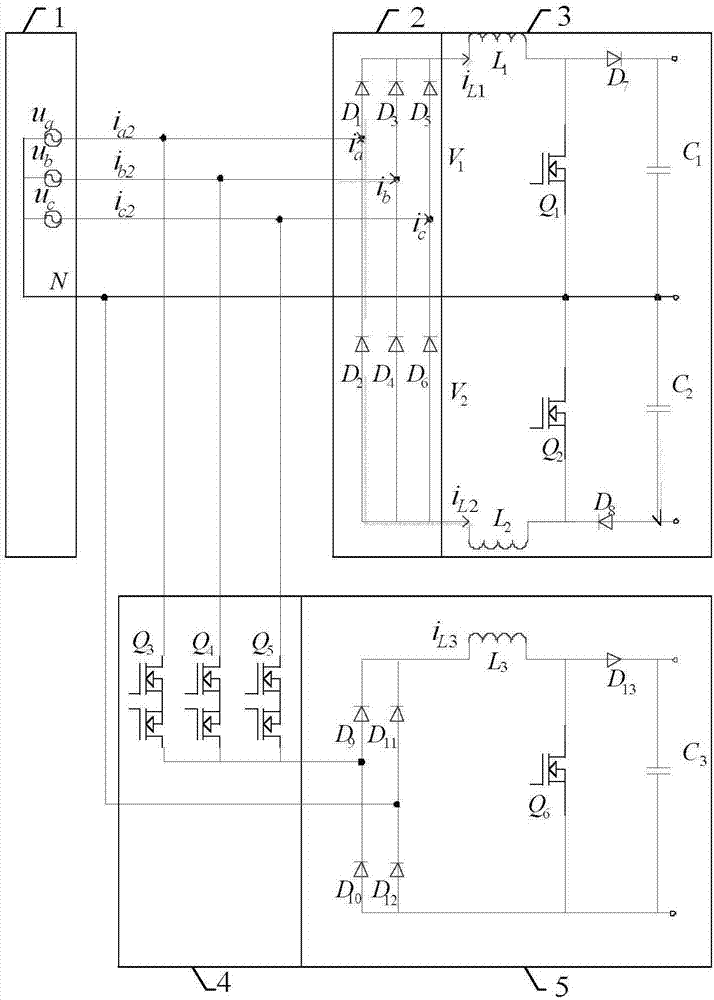
[0033] The three-phase double-half-wave boost PFC power factor correction of the present invention adopts three-phase half-wave rectification combined with two boost switch tubes, the circuit works in the continuous mode of inductive current, and the waveform compensation circuit is input to the three-phase double-half-wave boost PFC power factor correction circuit The middle 2 / 4 part of the current (-30° to 30°, 150° to 210°) is compensated so that the phase input current is a complete sine wave to achieve complete power factor correction.

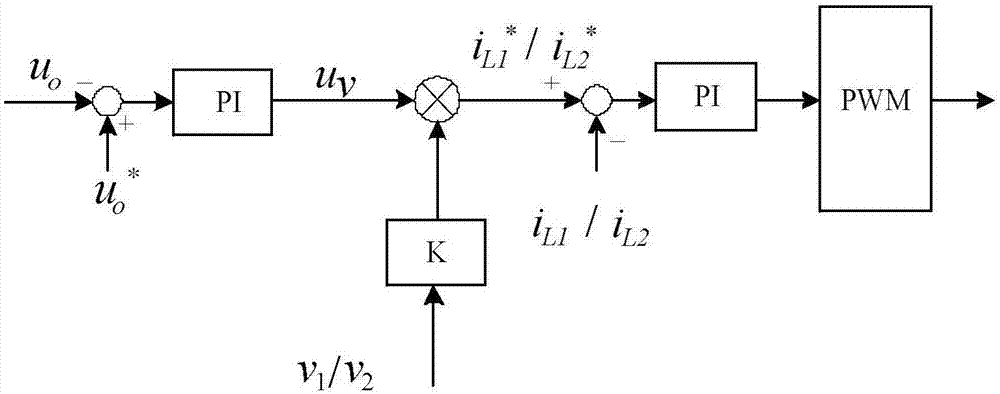
[0034] Such as figure 2 Shown, the output voltage sample value u 0 and a given value u 0 * After making a difference, it is adjusted by PI to form an inner loop current amplitude signal u v , which is multiplied by the unit half-wave rectified voltage signal to obtain the given signal of the inner loop i L1 * / i L2...


PUM


Abstract

The invention discloses a rectifier and a control method thereof, and belongs to the technical field of high power factor rectification. The rectifier comprises a three-phase voltage source circuit (1), a three-phase uncontrolled rectification circuit (2), two symmetric boost circuits (3), a third harmonic voltage generation circuit (4) and an H-bridge boost power factor correction (PFC) circuit (5), wherein double half-wave boost PFCs respectively generate steamed bread wave phase current waveforms at 30-150 degrees and 210-330 degrees within a period, a waveform compensation circuit can be switched to the corresponding phase when a certain phase current lacks, the phase current waveform which is insufficient is compensated, so that an input current is changed to a standard sine wave, and a converter works in a unit power factor rectification state. The rectifier can be used for a three-phase AC / DC conversion circuit having the PFC function, and the topological structure is simple and is convenient to control and easy to implement.

Description

technical field [0001] The invention relates to a rectifier and a control method thereof, belonging to the technical field of high power factor rectification. Background technique [0002] Power Factor Correction Technique (Power Factor Correction Technique) is a basic technology in the field of power electronics and industry. It is used to suppress harmonic pollution and reduce the harm caused by high-order current harmonics to the power grid and various electrical equipment. With the increase of electrical equipment, the requirements of high efficiency, high power density and high power factor are also put forward for the power converter. Therefore, various new PFC conversion topologies have also emerged as the times require. [0003] There are two types of power factor correction technology: passive power factor correction and active power factor correction. Passive power factor correction uses passive components, such as LC filters. Although the circuit structure is sim...

Claims


Application Information

Patent Timeline
Patent Type & Authority Applications(China)
IPC IPC(8): H02M7/06H02M3/07H02M1/42H02M1/14
CPCH02M1/14H02M1/4216H02M1/4225H02M1/4233H02M3/07H02M7/06Y02B70/10
Inventor 李金玉龚春英周烨
Owner NANJING UNIV OF AERONAUTICS & ASTRONAUTICS
Why Eureka
Try Eureka