
Multi-array camera imaging system and method therefor

一种成像器、渲染系统的技术,应用在电视系统的零部件、图像采集、图像分析等方向,能够解决成像系统需求尚未得到满足、资金和运营费用高、限制观看体验丰富性等问题,达到克服时延和带宽问题、高速采集与渲染、费用昂贵的效果

Inactive Publication Date: 2017-12-12
AQUETI INC
View PDF3 Cites 4 Cited by
  • Summary
  • Abstract
  • Description
  • Claims
  • Application Information

AI Technical Summary

Problems solved by technology

In addition to incurring prohibitive capital and operating expenses, this approach also limits the "richness" of the viewing experience
[0012] To date, there is an unmet need for imaging systems that simultaneously deliver high-resolution images

Method used


Image

  • Multi-array camera imaging system and method therefor
  • Multi-array camera imaging system and method therefor
  • Multi-array camera imaging system and method therefor

Examples


Embodiment Construction

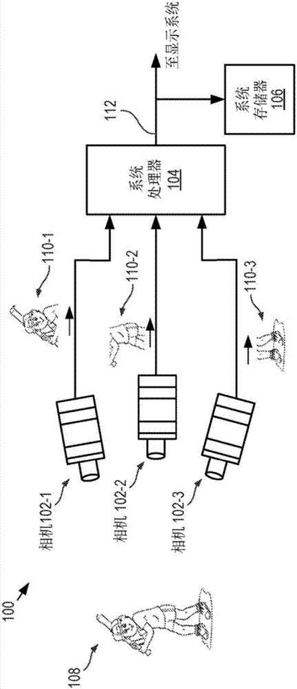
[0027] Figure 1A -B are schematic diagrams of a conventional array camera and a single miniature camera of the array, respectively. The array camera 100 includes a plurality of miniature cameras 102 - 1 to 102 - 3 , a system processor 104 and a system memory 106 . The array camera 100 is typical of prior art multi-sensor array cameras, where the sensor array resides in each miniature camera.

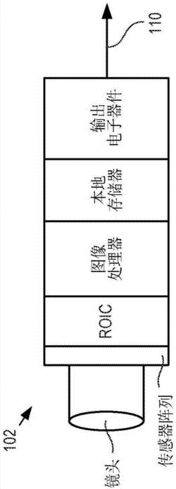
[0028]Each of the micro cameras 102-1 to 102-3 (collectively referred to as micro cameras 102) is a conventional digital video camera with an independent sensor array, image processing capability and memory. Each miniature camera 102 includes an objective lens, sensor array, readout integrated circuit (ROIC), image processor, local memory, and output electronics. The miniature cameras 102 are configured such that each camera can provide a video stream of a different portion of the scene 108 .

[0029] In each video frame of the video stream, the objective lens of each micro-camera 102...


PUM


Abstract

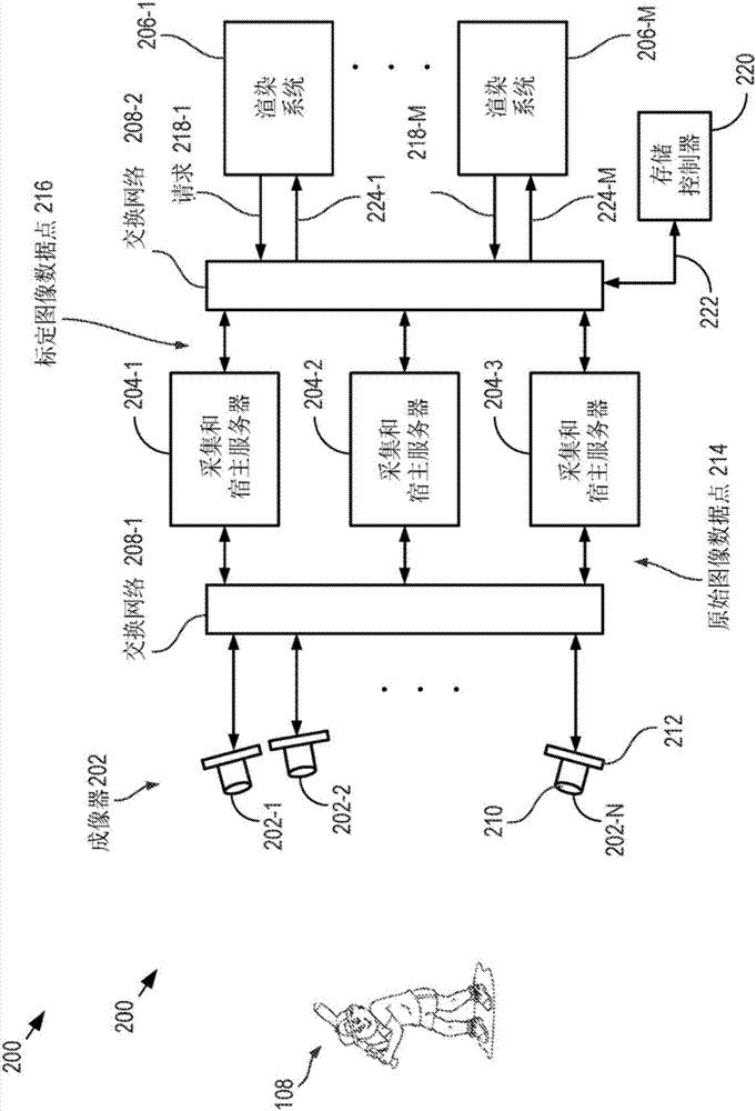
An imaging system and method for enabling the capture and rendering of an image without the latency and bandwidth requirements of the prior art is presented. Embodiments of the present invention employ a plurality of imagers that provide image data to a plurality of capture and hosting servers to which they are connected via a first communications bus. One or more rendering systems are interconnected to the plurality of servers via a second communications bus. The servers perform parallel processing of only raw image data necessary to satisfy individual rendering requests from the rendering systems. Since image processing is performed only on the image data required to render the particular view of interest, an entire high- resolution image is not formed to satisfy the rendering request and the desired image can be rendered with less latency and requires less bandwidth for transmission to the rendering system.

Description

[0001] Cross References to Related Applications [0002] This case claims priority to U.S. Provisional Patent Application Serial No. 62 / 132,861 (Attorney Docket: 3034-003PR1), filed March 13, 2015, which is hereby incorporated herein. In the event of any contradiction or inconsistency in the language between this application and one or more patent cases that have been incorporated by reference in this application and may affect the content of this application's claim interpretation, the claims in this case shall be interpreted in accordance with the Language remains consistent. technical field [0003] The present invention relates to imaging, and more particularly to imaging with a camera system having multiple focal plane arrays. Background technique [0004] Before the development of digital imaging systems, cameras were based on lenses and film emulsions located in the focal plane of the lenses. An optical image of the scene is projected onto the emulsion, where it is ...

Claims


Application Information

Patent Timeline
Patent Type & Authority Applications(China)
IPC IPC(8): H04N5/232H04N5/225G06T15/20
CPCG06T15/205H04N23/54H04N23/661H04N23/951H04N23/80G06T1/0007G06T3/4038H04N23/45G06T7/80G06T7/97
Inventor S·T·麦凯恩D·J·白瑞迪
Owner AQUETI INC
Learn More