Electroencephalogram cap

An EEG cap and brain electrode technology, applied in the field of EEG caps, can solve the problems of not being able to replace one person at a time, replacing water-absorbing materials, troublesome gauze and rubber bands, and not being able to fix the auxiliary electrodes well.

Pending Publication Date: 2017-12-15
汪子锋
View PDF0 Cites 20 Cited by
  • Summary
  • Abstract
  • Description
  • Claims
  • Application Information

AI Technical Summary

Problems solved by technology

The disadvantage of this method is: due to the small electrode body, it is very troublesome to replace the water-absorbing material, gauze and rubber ring, especially when there are many patients, there is no time to replace them one by one, and it is impossible to replace them one by one, which is easy to cause infection. Cross-infection is more likely to occur in patients with trauma
[0013] C. The connection between the traditional brain electrode support plate and the electrode beam is realized through the movable bolt, but the movable bolt can only use the supporting plate to move in a certain angle with the movable bolt as the center of the circle. In actual use, the moving direction of the supporting plate It moves in any direction with the change of head shape of different patients, which leads to poor auxiliary electrode fixation
[0014] D. Traditional brain electrodes can only be applied to EEG caps made of soft materials (hard materials can easily cause the placed brain electrodes to fall off when adjusting the position of the brain electrodes, making it more difficult for doctors to work), so they cannot Suitable for automatic EEG caps made of hard materials

Method used


Image

  • Electroencephalogram cap
  • Electroencephalogram cap
  • Electroencephalogram cap

Examples


Embodiment Construction

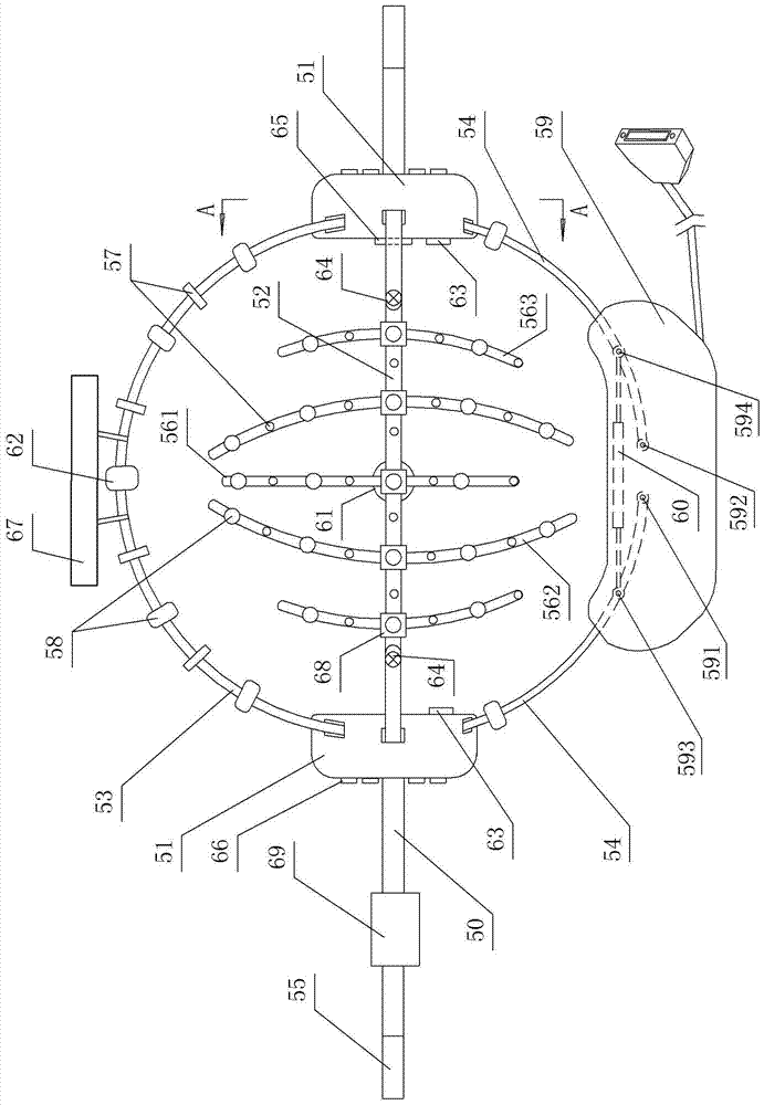
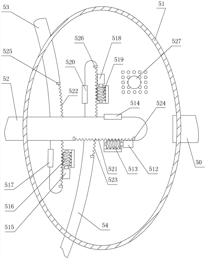
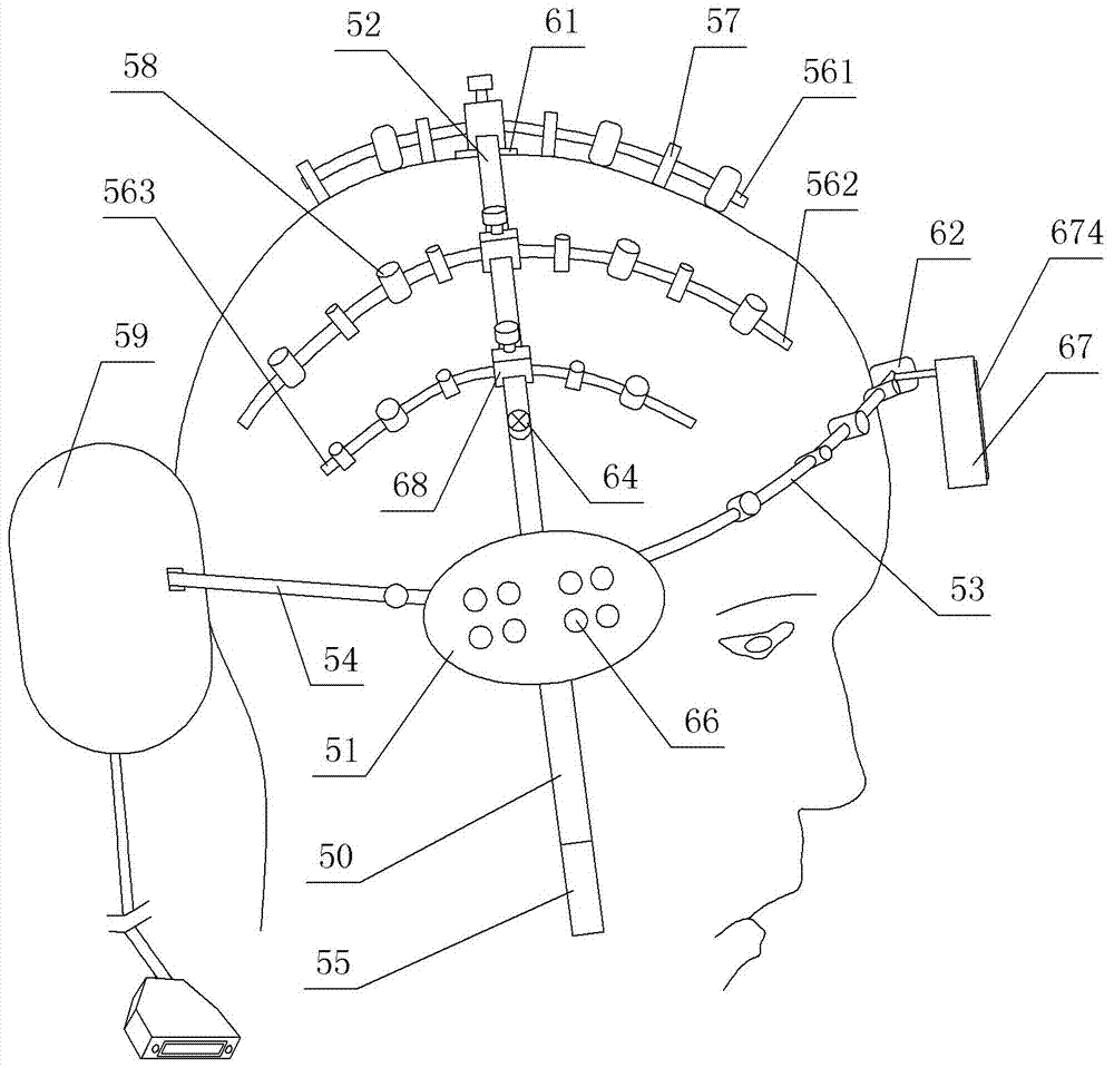
[0081] see Figure 1 to Figure 13 , in the figure, the EEG cap contains a cap body and a control circuit, and the cap body contains two ear supports, a top support bar 52, a front support bar 53 and a rear support bar 54, and the two ear support bodies are respectively arranged on At the two ears of people, the top support rod 52, the front support rod 53 and the rear support rod 54 are all arc rods, and the two ends of the top support rod 52, the front support rod 53 and the rear support rod 54 are respectively installed On the two ear supports, the top support rod 52 spans above the top of the human head from left to right, the front support rod 53 spans from left to right in front of the human forehead, and the rear support rod 54 spans from left to right. To the right, it straddles the back of the back of the human brain, an elastic connecting belt 50 is connected between the two ear supports, and 5 electrode fixing rods are cross-connected to the top supporting rod 52, an...


PUM


Abstract

The invention relates to an electroencephalogram cap and a method for establishing a three-dimensional head-shaped electroencephalogram and a brain oxygen distribution map. The electroencephalogram cap comprises a cap body and a control circuit, wherein the cap body is formed by two ear part supporting bodies, a top supporting rod, a front part supporting rod and a back part supporting rod; two ends of the top, front and back part supporting rods are respectively arranged on the two ear part supporting bodies; the top, front and back part supporting rods span places over the head, in front of the head and behind the head from left to right; the top supporting rod is in a cross-connection with N electrode fixing rods; the electrode fixing rods, the front part supporting rods and the back part supporting rods are all equipped with brain electrodes; and the brain electrodes are connected with the control circuit. The method for establishing electroencephalogram and the brain oxygen distribution map forms a scalp surface three-dimensional model according to the electroencephalogram cap and position parameters of the scalp surface, and then obtains an electroencephalogram and a brain oxygen distribution map matched with a practical head shape. The electroencephalogram cap is convenient to use and can accurately collect signals and has strong anti-interference capability; and the electroencephalogram and the brain oxygen distribution map achieved according to the method has great authenticity.

Description

technical field [0001] The invention relates to an electroencephalogram monitoring device, in particular to an electroencephalogram cap. Background technique [0002] Brain waves are formed by the sum of the synchronous post-synaptic potentials of a large number of neurons when the brain is active. It is the overall reflection of the electrophysiological activities of brain nerve cells on the surface of the cerebral cortex or scalp. The monitoring of brain waves has been widely used. in existing clinical practice. [0003] In traditional brainwave monitoring equipment, the wearing process of brain electrodes is very complicated, and the operation process is cumbersome and lengthy. Under normal circumstances, the patient should first wash his hair the day before the examination to remove the head oil; during the examination, first wear a special elastic cap on the head, and then use a comb to separate the hair where the brain electrodes are placed, exposing the scalp , wipe...

Claims


Application Information

Patent Timeline
Patent Type & Authority Applications(China)
IPC IPC(8): A61B5/0476A61B5/0478A61B5/0484A61B5/1455A61B5/01
CPCA61B5/01A61B5/14553A61B5/6803A61B5/6814A61B5/6815A61B5/6843A61B5/72A61B5/291A61B5/369A61B5/378A61B5/38
Inventor 汪子锋
Owner 汪子锋
Why Eureka
Try Eureka