Pipeline inner wall cleaning device

A technology for cleaning inner walls and pipes, applied in the direction of cleaning hollow objects, cleaning methods and utensils, chemical instruments and methods, etc., can solve problems such as pipe blockage, achieve the effects of preventing inconsistencies, preventing water pipe entanglement, and high cleaning efficiency

Inactive Publication Date: 2017-12-15
成都兆丰斯诺科技有限公司
View PDF2 Cites 25 Cited by
  • Summary
  • Abstract
  • Description
  • Claims
  • Application Information

AI Technical Summary

Problems solved by technology

[0003] The purpose of the present invention is to provide a cleaning device for the inner wall of the pipeline, which is used

Method used


Image

  • Pipeline inner wall cleaning device
  • Pipeline inner wall cleaning device
  • Pipeline inner wall cleaning device

Examples


Embodiment 1

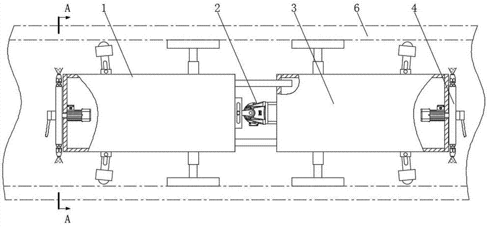
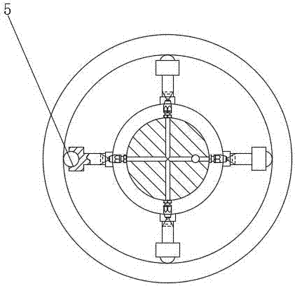
[0025] combined with Figure 1-4 As shown, a pipeline inner wall cleaning device includes a front traveling mechanism 1, a telescopic mechanism 2, and a rear traveling mechanism 3 connected sequentially from front to back; A cleaning mechanism 4 is provided at the diverging ends of the front traveling mechanism 1 and the rear traveling mechanism 3; In this embodiment, the front traveling mechanism 1 and the rear traveling mechanism 3 both include a cylinder body, a fixed arm assembly, and a walking roller assembly; and the retractable fixed arm that loosens the inner wall of the pipeline; the walking roller assembly includes a plurality of walking arms that are connected to the cylinder and are evenly distributed radially along the outer circular surface of the cylinder, and the end of the walking arm that contacts the inner wall of the pipeline is rotatably connected with a roller , the telescopic mechanism 2 adopts a linear oil cylinder, that is, the cylinder body of the oi...

Embodiment 2

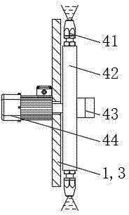
[0029] For implementing the present invention better, realize cleaning pipeline inner wall without dead angle, on the basis of embodiment 1, in conjunction with attached Figure 1-4 Further, the cleaning mechanism 4 includes a first motor 44 fixedly connected to the front end of the front traveling mechanism 1 or the rear end of the rear traveling mechanism 3, a disc 42 fixedly connected to the output shaft of the first motor 44, and a disc 42 detachably connected to the disc 42 the high-pressure nozzle 41 on the outer surface; the disc 42 is provided with a water channel with one end communicating with the high-pressure nozzle 41 and the other end communicating with the external water source.

Embodiment 3

[0031] In order to better implement the present invention, prevent the water pipe from being entangled due to the rotation of the motor, on the basis of Embodiment 2, in combination with the attached Figure 1-4 Further, the end surface of the disc 42 away from the first motor 44 is detachably connected with a rotary joint 43, one end of the rotary joint 43 communicates with the water channel in the disc 42, and the other end of the rotary joint 43 communicates with an external water source. In this embodiment, the model of the rotary joint 43 is GP-621.


PUM


Abstract

The invention discloses a pipeline inner wall cleaning device, which relates to the field of pipeline cleaning, and comprises a front traveling mechanism, a telescopic mechanism and a rear traveling mechanism which are sequentially connected from front to back; ; The diverging ends of the front traveling mechanism and the rear traveling mechanism are provided with a cleaning mechanism; the cleaning mechanism is provided with a high-pressure nozzle connected to an external water source, and the outlet of the high-pressure nozzle faces the inner wall of the pipeline. The cleaning mechanism includes a first motor fixedly connected to the front end of the front traveling mechanism or the rear end of the rear traveling mechanism, a disc fixedly connected to the output shaft of the first motor, and a high-pressure nozzle detachably connected to the outer surface of the disc; A water channel is provided with one end communicating with the high-pressure nozzle and the other end communicating with the external water source. The present invention realizes the effect of using the high-pressure water jet to strip and clean the dirt on the inner surface of the pipeline by arranging the traveling mechanism and the high-pressure nozzle.

Description

technical field [0001] The invention relates to the field of pipeline cleaning, in particular to a pipeline inner wall cleaning device. Background technique [0002] For pipelines that have been used for a long time, the solidification of oil sludge and rust in the pipeline will cause the diameter of the original pipeline to become smaller; the sludge in the pipeline will produce hydrogen sulfide gas, which will cause environmental pollution and easily cause explosion; the acid and alkali substances in the waste water will easily corrode the pipeline wall; Unscheduled removal of foreign matter in the pipeline will cause pipeline blockage; steel pipes, steel plates, stainless steel, etc., which are raw materials for metal pipelines, will form rolling skin during rolling; pipelines will form rust, welding slag and anti-corrosion coatings during the process of manufacturing, storage, transportation and installation. Oil-based antirust agent, dust, sand, cement, insulation mater...

Claims


Application Information

Patent Timeline
IPC IPC(8): B08B9/032B08B9/051
CPCB08B9/0321B08B9/051
Inventor 张远
Owner 成都兆丰斯诺科技有限公司
Why Eureka
Try Eureka