Riveting die used for ball head rivet and sheet metal part

A technology for sheet metal parts and sheet metal parts, which is applied in the field of riveting molds, can solve the problems that the ejection force and torsion force cannot meet the requirements of customers, the product quality cannot be guaranteed, and the product stability is poor. The effect of easy access

Pending Publication Date: 2017-12-15
SHANDONG AOLIN CAR FITTINGS
View PDF5 Cites 1 Cited by
  • Summary
  • Abstract
  • Description
  • Claims
  • Application Information

AI Technical Summary

Problems solved by technology

However, for the riveting of ball rivets and sheet metal parts, if the commonly used riveting mold is used, the ejection force and tor

Method used


Image

  • Riveting die used for ball head rivet and sheet metal part
  • Riveting die used for ball head rivet and sheet metal part
  • Riveting die used for ball head rivet and sheet metal part

Examples


Embodiment 1

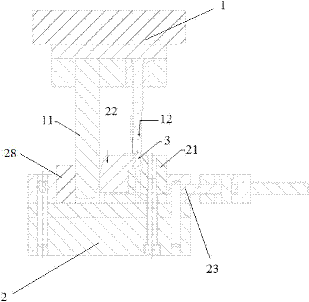
[0022] A riveting die for ball rivets and sheet metal parts, the structure of which is as follows figure 1 As shown, it includes an upper mold 1 and a lower mold 2. The lower surface of the upper mold 1 is provided with a riveting punch 12 for pressing the ball rivet 3 and the sheet metal to realize riveting, and the upper surface of the lower mold 2 is processed with a clamping arrangement. The clamping block assembly of the ball rivet 3 and the sheet metal part, the clamping block assembly includes a static clamping block 21 and a movable clamping block 22 that are butted and matched with each other to form a riveting cavity that matches the ball rivet 3 and the sheet metal part, and the lower die 2 is provided with There is a guide hole along the horizontal direction, and a push rod 23 moving along it is installed in the guide hole. One end of the push rod 23 extends out of the lower die 2, and the other end is connected to the movable clamp block 22, and drives the movable ...

Embodiment 2

[0025] On the basis of embodiment 1, this embodiment is further set to:

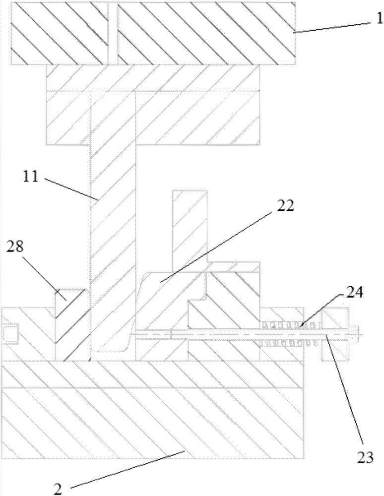
[0026] A baffle 25 is connected to the end of the push rod 23 , and a return spring 24 is also provided between the baffle 25 and the lower die 2 .

Embodiment 3

[0028] On the basis of embodiment 2, this embodiment is further set to:

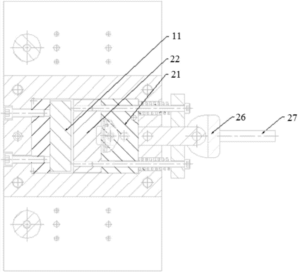
[0029] The side of lower die 2 is also fixedly provided with a positioning seat, and a clamping cam 26 is rotated on the positioning seat. The cam surface of this clamping cam 26 is against the baffle plate 25, and the clamping cam 26 is also equipped with a handle 27 outwards.


PUM


Abstract

The invention relates to a riveting die used for a ball head rivet and a sheet metal part. The riveting die comprises an upper die and a lower die. A riveting punch used for pressing the ball head rivet and the sheet metal part for achieving riveting is arranged on the lower surface of the upper die. A clamping block assembly used for clamping and placing the ball head rivet and the sheet metal part is machined on the upper surface of the lower die. The clamping block assembly comprises a static clamping block and a movable clamping block which are in butt joint and are matched to form a riveting cavity matched with the ball head rivet and the sheet metal part. A guide hole is formed in the lower die in the horizontal direction, and a push rod moving along the guide hole is installed in the guide hole. One end of the push rod stretches out of the lower die, and the other end of the push rod is connected with the movable clamping block and drives the movable clamping block to move on the lower die. Compared with the prior art, the contact area between the ball head rivet and the clamping block assembly is large, during riveting punching, the ball head deformation of the ball head rivet is small, the size is stable, the riveting strength is also greatly improved, and the ejecting force and torsion are improved, are stable and the like.

Description

technical field [0001] The invention relates to a mold, in particular to a riveting mold used for ball rivets and sheet metal parts. Background technique [0002] Riveting is a simple and practical technical means, and it has been widely used in the company's daily production. Its advantages are light weight mold, low cost and simple process. However, for the riveting of ball rivets and sheet metal parts, if the commonly used riveting mold is used, the ejection force and torque may not meet the customer's requirements, the product stability is poor, and the quality of riveted products cannot be guaranteed. Contents of the invention [0003] The object of the present invention is to provide a riveting die for ball rivets and sheet metal parts in order to overcome the defects in the prior art. [0004] The purpose of the present invention can be achieved through the following technical solutions: [0005] A riveting die for ball rivets and sheet metal parts, comprising an ...

Claims


Application Information

Patent Timeline
IPC IPC(8): B21J15/38B21J15/42
CPCB21J15/38B21J15/42Y02P70/10
Inventor 陆汉生
Owner SHANDONG AOLIN CAR FITTINGS
Why Eureka
Try Eureka