
Flexible fixture device for machining aviation complex thin-walled parts and fabrication method of flexible fixture device

A technology of flexible fixtures and fixture devices, applied in the field of processing and manufacturing, can solve problems such as inability to meet assembly requirements, and achieve the effects of simple structure, convenient operation, high interchangeability and modularization

Pending Publication Date: 2017-12-15
SHENYANG MASCH TOOL CO LTD
View PDF8 Cites 17 Cited by
  • Summary
  • Abstract
  • Description
  • Claims
  • Application Information

AI Technical Summary

Problems solved by technology

At the same time, with the emergence of more and more new parts, new requirements are put forward for the performance and structure of the fixture. The old assembly tooling can no longer meet the assembly requirements. A simple structure, strong adaptability and high flexibility is needed. New flexible fixture

Method used


Image

  • Flexible fixture device for machining aviation complex thin-walled parts and fabrication method of flexible fixture device
  • Flexible fixture device for machining aviation complex thin-walled parts and fabrication method of flexible fixture device
  • Flexible fixture device for machining aviation complex thin-walled parts and fabrication method of flexible fixture device

Examples


Embodiment Construction

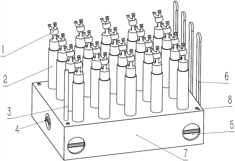
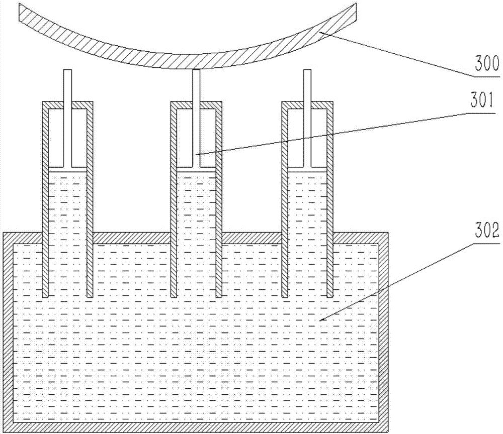
[0027] In the drawings: 1--Universal head; 2--Piston; 3--Auxiliary support rod; 4--Electromagnetic locking device; 5--Manual electromagnet; 6--Detection device; 7--Clamp box; 8--Machining reference zero mark; image 3 Middle 300--thin-walled workpiece; 301--piston rod; 302--liquid; 400--solenoid valve in Figure 4; 401--valve body; 402--connecting rod in X direction; 403--connecting rod in Y direction; 404—overflow hole; A, B, and C are three selected detection points in Fig. 5, a, b, and c are each point in the detection device 6, and L1, L2, and L3 are obtained after measurement and processing The relative height of each point.

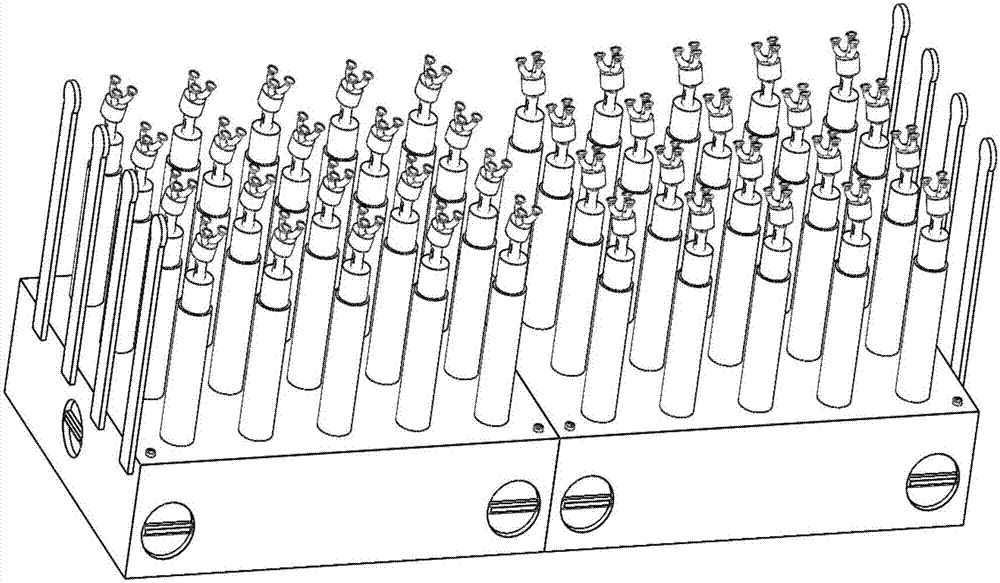
[0028] The present invention is a kind of flexible fixture device for processing aviation complex thin-walled parts, such as figure 1 As shown, the flexible fixture device consists of 2 flexible fixture modules.

[0029] A single flexible fixture module such as figure 2 As shown, three small rubber suction cups are fixed on the upper end of the ...


PUM


Abstract

The invention provides a flexible fixture device for machining aviation complex thin-walled parts and a fabrication method of the flexible fixture device. The flexible fixture device is characterized by comprising a plurality of fixture module structures, according to the fixture module structures, universal joints are installed at the tops of pistons, the multiple pistons are fixedly arranged in a fixture box body, one side of the fixture box body is provided with detection devices, the box corners are provided with an assistant supporting rod and machining reference zero-position marks, the box body wall is provided with an electromagnetic locking device and hand-actuated electromagnets, liquids are stored in the fixture box body, and liquids in piston cavities and the liquids in the fixture box body are circulated, and fixture modules are formed. The fabrication method comprises the following steps that firstly, the universal joints are installed on piston rods, the pistons are installed on the fixture box body, the assistant supporting rod is installed at one of the box corners, the detection devices are installed on the side faces of the fixture box body, then the flexible fixture modules are assembled, and the multiple flexible fixture modules which are of the same shapes as those of the thin-walled parts are assembled into the fixture device with the universal joints being in high-low transition and the edges being staggered. The flexible fixture device is simple in structure, convenient to operate, low in fabrication cost and high in interchangeability and modularization degree and has certain degrees of automation characteristics, and by means of the flexible fixture device and the fabrication method of the flexible fixture device, the production efficiency is greatly improved.

Description

technical field [0001] The invention belongs to the field of processing and manufacturing, and relates to a design, manufacture and use method of a flexible clamping device used in the processing of aviation complex thin-walled parts. Background technique [0002] Aviation industry is a strategic industry of national economy and national defense construction, and it is a concentrated expression of a country's industrial technology. The role of the aircraft skin is to maintain the shape of the aircraft so that it has good aerodynamic characteristics. Aircraft skin is a typical thin-walled part, with complex structure, low relative rigidity, large machining allowance, poor workmanship, and easy deformation due to force during processing. [0003] Traditional thin-wall parts assembly tooling mostly adopts rigid structure, and the assembly mode adopts one-to-one mode, that is, one component corresponds to one frame, so a large number of tooling needs to be designed and manufact...

Claims


Application Information

Patent Timeline
IPC IPC(8): B23Q3/06B23Q3/08B23Q3/154
CPCB23Q3/065B23Q3/082B23Q3/1543
Inventor 罗和平汲军刘永吉张童吕博李志丹张云峰李多祥白义索霄峰王帝白雅静
Owner SHENYANG MASCH TOOL CO LTD
Learn More