Drilling cutting device for computer production

A cutting device and computer technology, applied in transportation and packaging, object supply, metal processing, etc., can solve problems such as low work efficiency and achieve good results

Active Publication Date: 2017-12-15
合肥万伟达信息科技有限公司
7 Cites 20 Cited by

AI-Extracted Technical Summary

Problems solved by technology

[0004] Aiming at the deficiencies of the prior art, the present invention provides a drilling and cutting device for computer product...

Abstract

The invention discloses a drilling cutting device for computer production. The drilling cutting device for the computer production comprises a shell; the left side of the bottom of the inner wall of the shell is fixedly connected with a first motor; an output shaft of the first motor is fixedly connected with a first belt pulley; the surface of the first belt pulley is in transmission connection with a second belt pulley through the first belt pulley; the axis of the second belt pulley is fixedly connected with a first driving wheel; the surface of the first driving wheel is in transmission connection with a second driving wheel through a driving belt; and the left side of the inner wall of the shell is fixedly connected with a fixed plate. The invention relates to the technical field of computer production. According to the drilling cutting device for the computer production, the driving belt is driven to rotate through the first motor; a material pressing device presses a plate tightly, and materials are fed continuously; a second motor drives a movement device to move so as to drive a third motor to move reciprocally to drill the plate; a fourth motor drives a cam to rotate to drive a cutting machine to move to drill and cut the plate synchronously; the machining time is shortened; and the work efficiency is improved.

Application Domain

Technology Topic

Image

  • Drilling cutting device for computer production
  • Drilling cutting device for computer production
  • Drilling cutting device for computer production

Examples

  • Experimental program(1)

Example Embodiment

[0023] The technical solutions in the embodiments of the present invention will be clearly and completely described below in conjunction with the accompanying drawings in the embodiments of the present invention. Obviously, the described embodiments are only a part of the embodiments of the present invention, rather than all the embodiments. Based on the embodiments of the present invention, all other embodiments obtained by those of ordinary skill in the art without creative work shall fall within the protection scope of the present invention.
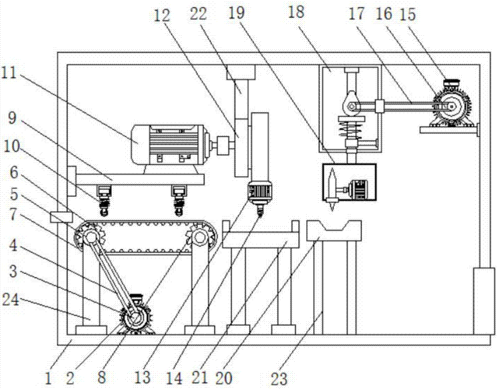
[0024] See Figure 1-4 , The present invention provides a technical solution: a drilling and cutting device for computer production, comprising a housing 1, the left side of the bottom of the inner wall of the housing 1 is fixedly connected with a first motor 2, and the output shaft of the first motor 2 is fixedly connected with The first pulley 3, the surface of the first pulley 3 is connected to the second pulley 5 through the first belt 4, the axis of the second pulley 5 is fixedly connected to the first transmission wheel 6, and the surface of the first transmission wheel 3 passes through the transmission belt 7 The second transmission wheel 8 is connected in transmission. Both the first transmission wheel 6 and the second transmission wheel 8 are fixedly connected to the bottom of the inner wall of the housing 1 through a support column 24, and the left side of the inner wall of the housing 1 is fixedly connected with a fixing plate 9. And the fixed plate 9 is located above the conveyor belt 7, and the bottom of the fixed plate 9 is fixedly connected to the position corresponding to the transmission belt 7 with a pressing device 10, the top of the fixed plate 9 is fixedly connected with the second motor 11, and the top of the inner wall of the housing 1 is fixed The moving device 12 is connected, and the bottom of the moving device 12 is fixedly connected with a third motor 13, the output shaft of the third motor 13 is fixedly connected with a drill bit 14, and the inside of the housing 1 and located at the bottom of the third motor 13 is provided with a drill. The hole table 21 and both sides of the bottom of the drilling table 21 are fixedly connected with support rods 23. The bottom end of the support rod 23 is fixedly connected with the bottom of the inner wall of the housing 1, and the right side of the inner wall of the housing 1 is fixedly connected with a fourth motor 15 , The output shaft of the fourth motor 15 is fixedly connected to the third pulley 16, the surface of the third pulley 16 is connected to the cutting device 18 through the second belt 17, and the top of the cutting device 18 is fixedly connected to the top of the inner wall of the housing 1, A cutting machine 19 is fixedly connected to the bottom of the cutting device 18, and a cutting table 20 is arranged inside the housing 1 and located at the bottom of the cutting machine 19. The bottom of the cutting table 20 is fixedly connected to the bottom of the inner wall of the housing 1 through a support rod 23, The material device 10 includes a fixed seat 101, the top of the fixed seat 101 is fixedly connected to one side of the bottom of the support plate 9, the inside of the fixed seat 101 is movably connected with a bottom plate 102, and the bottom of the bottom plate 102 is fixedly connected with a movable rod 103, the movable rod 103 The end away from the bottom plate 102 penetrates the bottom of the fixing base 101 and extends to the outside of the fixing base 101, the movable rod 103 is located outside the fixing base 101 and is fixedly connected with a clamping plate 104, and the bottom of the clamping plate 104 is rotatably connected with a pressing roller 105 , The bottom of the fixed seat 101 and the surface of the movable rod 103 is fixedly connected to the limit plate 106, between the bottom of the limit plate 106 and the top of the card plate 104 and located on the surface of the movable rod 103, a spring 107 is fixedly connected to the movement device 12 It includes a bottom plate 121, and the top of the bottom plate 121 is fixedly connected with the top of the inner wall of the housing 1, the top of the bottom plate 121 is fixedly connected with a vertical rod 22, the top of the vertical rod 22 is fixedly connected with the top of the inner wall of the housing 1, and the surface of the bottom plate 121 is fixed Connected to the turntable 122, the center of the turntable 122 is rotatably connected with the bottom plate 121 through the central shaft 123, the surface of the turntable 122 is fixedly connected with a pusher 124, and the pusher 124 is connected with a rotating rod 125 through a slot drive. The right end is rotatably connected with the bottom plate 121 through a fixed rod 126, and the right end of the rotating rod 125 is fixedly connected with a gear plate 127. The bottom plate 121 is provided with a first movable rod 128 at one end away from the turntable 122. The first movable rod 128 is connected to the bottom plate through a fixed card 129 121 is movably connected, the arc surface of the gear plate 127 and the side of the first movable rod 128 close to the turntable 122 are respectively provided with clamping teeth and are mutually engaged. The cutting device 18 includes a frame 181, and the top of the housing is connected to the inner wall of the housing 1. The top of the frame body 181 is fixedly connected to the top of the inner wall of the frame body 181 is fixedly connected with a connecting rod 182, the bottom end of the connecting rod 182 is rotatably connected with a transmission shaft 183, the surface of the transmission shaft 183 is fixedly connected with a cam 184, and the transmission shaft 183 is away from the connecting rod 182 The fourth pulley 185 is fixedly connected to the fourth pulley 185, and the surface of the fourth pulley 185 is drivingly connected to the second belt 17. The bottom of the cam 184 is provided with a movable plate 186, and the bottom of the movable plate 186 is fixedly connected with a second movable rod 187, The bottom of the inner wall of the frame 181 is fixedly connected with a support rod 188, and the end of the support rod 188 away from the frame 181 is sleeved with the second movable rod 187. The surface of the second movable rod 187 is located on the movable plate 186 and the support rod 188. A spring 189 is fixedly connected therebetween. The bottom end of the second movable rod 187 penetrates the frame 181 and extends to the outside of the frame 181. The end of the second movable rod 187 located outside the frame 181 is fixedly connected to the cutter 19.
[0025] When working, the sheet is fed in from the inlet on the left side of the housing 1, the first motor 2 works to drive the first pulley 3 to rotate, the first pulley 3 drives the second pulley 5 to rotate through the first belt 4, and the second pulley 5 Drive the first transmission wheel 6 to rotate and drive the conveyor belt 7 to rotate. The plate is pressed by the pressing roller 105 to continue feeding. The second motor 11 drives the central shaft 123 to rotate, drives the turntable 122 to rotate, and drives the rotating rod 125 to rotate through the pusher 124 to drive The first movable rod 128 reciprocates up and down to drive the third motor 13 to reciprocate up and down. The third motor 13 works to drive the drill bit 14 to rotate to intermittently perforate the plate. The fourth motor 15 works to drive the third pulley 16 to rotate, and the third pulley 16 The second belt 17 drives the fourth pulley 185 to rotate, thereby driving the cam 184 to rotate, driving the movable plate 186 to reciprocate up and down, and driving the second movable rod 187 to move, thereby driving the cutting machine 19 to move to perform intermittent cutting of the plate to complete the alignment. Punching and cutting of plates.
[0026] It should be noted that in this article, relational terms such as first and second are only used to distinguish one entity or operation from another entity or operation, and do not necessarily require or imply one of these entities or operations. There is any such actual relationship or order between. Moreover, the terms "include", "include" or any other variants thereof are intended to cover non-exclusive inclusion, so that a process, method, article or device including a series of elements not only includes those elements, but also includes those that are not explicitly listed Other elements of, or also include elements inherent to this process, method, article or equipment. Without more restrictions. The sentence "including an element defined by ... does not exclude the existence of other identical elements in the process, method, article, or equipment including the element."
[0027] Although the embodiments of the present invention have been shown and described, those of ordinary skill in the art can understand that various changes, modifications, and substitutions can be made to these embodiments without departing from the principle and spirit of the present invention. And variations, the scope of the present invention is defined by the appended claims and their equivalents.

PUM

no PUM

Description & Claims & Application Information

We can also present the details of the Description, Claims and Application information to help users get a comprehensive understanding of the technical details of the patent, such as background art, summary of invention, brief description of drawings, description of embodiments, and other original content. On the other hand, users can also determine the specific scope of protection of the technology through the list of claims; as well as understand the changes in the life cycle of the technology with the presentation of the patent timeline. Login to view more.

Similar technology patents

Methods for treating hcv

InactiveUS20130273005A1Good effect很少和不太严重的副作用BiocideDipeptide ingredientsHenipavirus InfectionsRegimen
Owner:GILEAD PHARMASSET LLC

Combination of sulfonamide compound and tafluprost

InactiveUS20140018350A1Good effectReduce the impactBiocideOintment deliveryTherapy medicationBenzyl group
Owner:SANTEN PHARMA CO LTD +1

Classification and recommendation of technical efficacy words

Why Eureka
Try Eureka