Hoisting vehicle for replacing long and heavy parts of high-speed railway turnout and its replacement method

A technology for component replacement and hoisting vehicles, which is applied to the upper structure of the track, roads, tracks, etc., can solve the problems of high equipment cost, safety hazards, and long time consumption, and achieve the effects of saving on-site operation time, low equipment investment, and easy promotion

Active Publication Date: 2019-06-18
蔡钟博
View PDF6 Cites 1 Cited by
  • Summary
  • Abstract
  • Description
  • Claims
  • Application Information

AI Technical Summary

Problems solved by technology

[0002] In recent years, with the development of high-speed railways and the increase in passenger traffic, more and more long and heavy parts such as movable frogs, point rails, and basic rails have been repaired and replaced in turnouts of high-speed railway lines. Complex, limited by catenary interference, the long and heavy parts of high-speed rail turnouts are long and heavy, which leads to the fact that large-scale lifting equipment cannot be used when the long and heavy parts of high-speed rail turnouts are safely placed on both sides of the line and replaced safely. Currently, rail cranes are used Hoisting, there are disadvantages such as secondary hoisting of long and heavy parts of high-speed railway turnouts, high equipment costs, long time consumption, and potential safety hazards

Method used


Image

  • Hoisting vehicle for replacing long and heavy parts of high-speed railway turnout and its replacement method
  • Hoisting vehicle for replacing long and heavy parts of high-speed railway turnout and its replacement method
  • Hoisting vehicle for replacing long and heavy parts of high-speed railway turnout and its replacement method

Examples


Embodiment 1

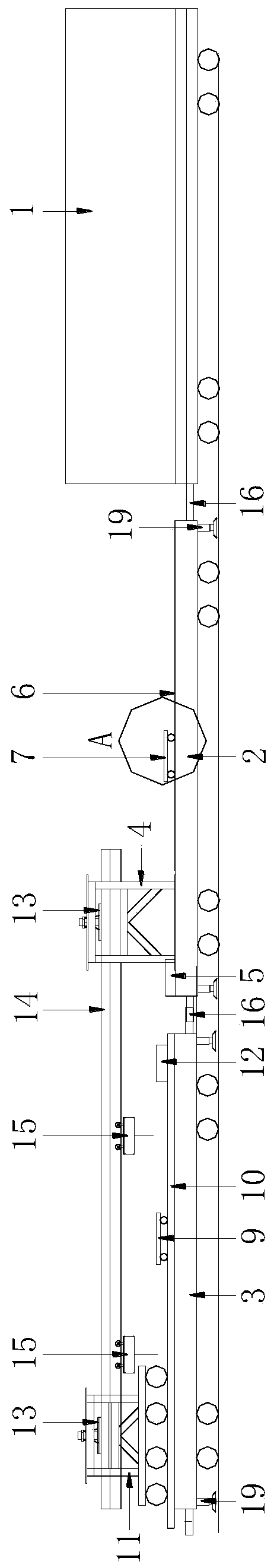
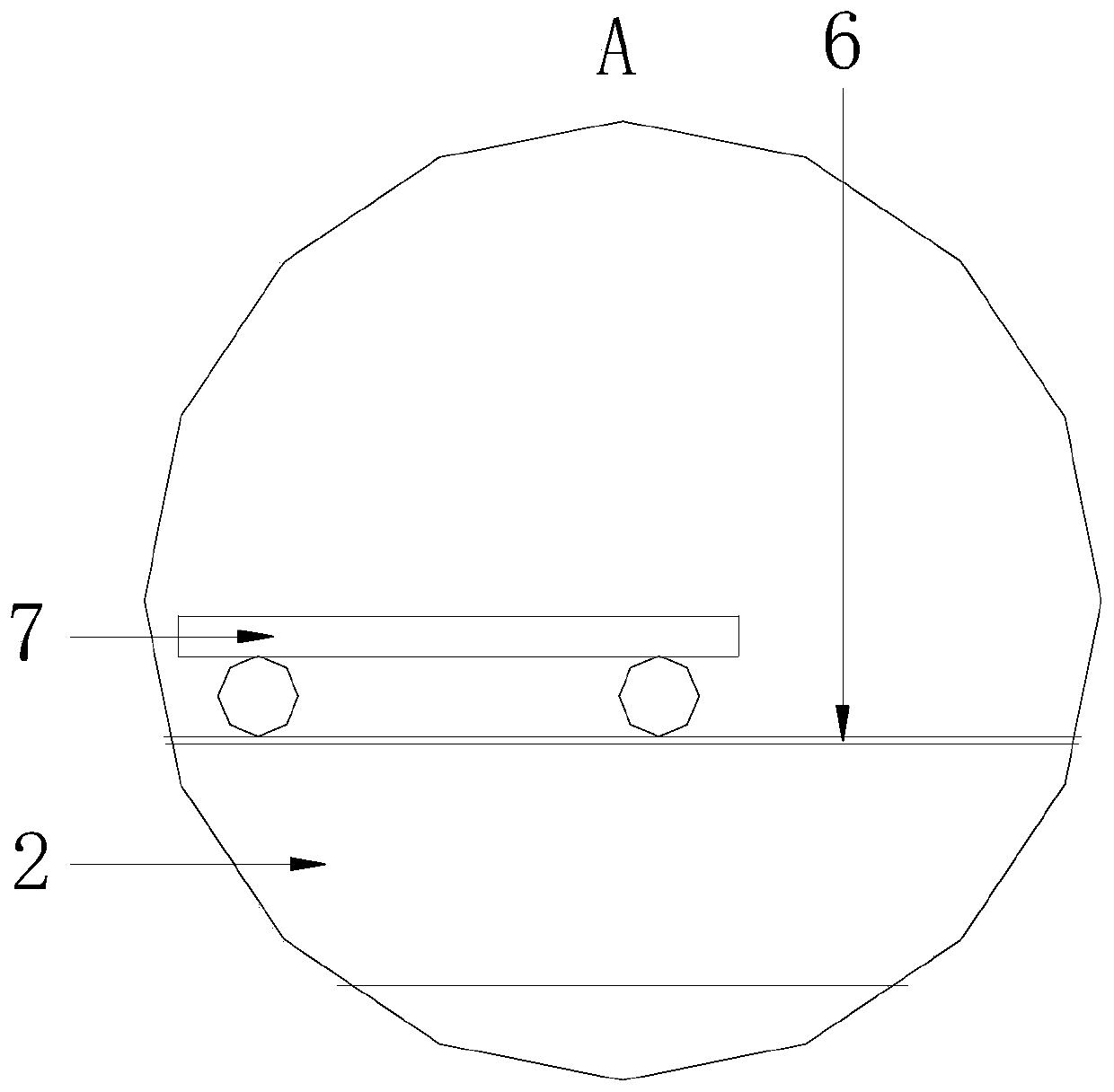
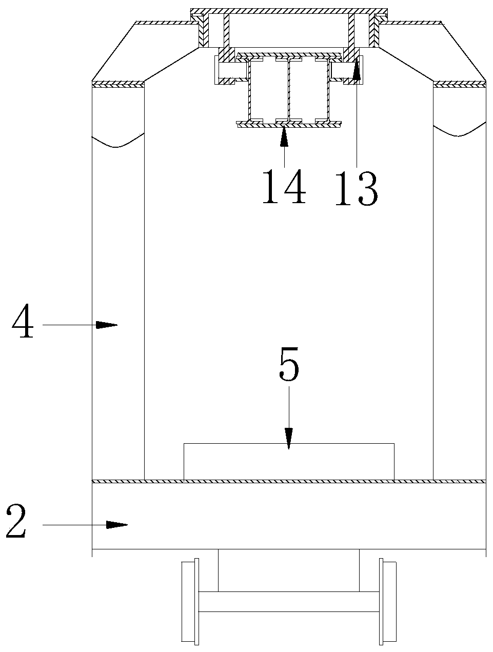
[0028] Embodiment 1: as Figure 1 to Figure 4As shown, the hoisting vehicle for replacing long and heavy parts of high-speed railway turnouts includes rail car 1, fixed gantry flat car 2 and movable gantry flat car 3 connected end to end through hooks 16, and fixed gantry flat car 1 and movable gantry flat car The bottom of both sides of the flat car 2 is vertically provided with a hydraulically telescopic support arm 19; the top of the tail of the fixed gantry flat car 2 is fixedly provided with a fixed gantry 4 and a fixed gantry flat car support frame 5; A pair of fixed gantry flat car tracks 6 are arranged on the top of the fixed gantry flat car 2 on the inner side, and a fixed gantry small flat car 7 that moves back and forth along the fixed gantry small flat car track 6 is arranged on the fixed gantry small flat car track 6; The top surface of the gantry flat car support frame 5 is at the same level as the top surface of the fixed gantry flat car 7; a pair of movable gan...

Embodiment 2

[0029] Embodiment 2: as Figure 5 As shown, the movable center rail switch replacement hoisting vehicle includes a rail car 1, a fixed gantry flat car 2 and a movable gantry flat car 3 connected end-to-end through a hook 16. The difference is that the fixed gantry flat car 2 is composed of two fixed gantry assembly flat cars 2-1, and the bottom of each fixed gantry assembly flat car 2-1 is vertically provided with hydraulic telescopic support arms 19; The fixed gantry assembly flat car 2-1 at the tail end is fixed with a fixed gantry small flat car track 6; the fixed gantry 4 and the fixed gantry flat car support frame 5 are placed on the rearmost fixed gantry assembly flat car 2-1 top of the rear of the car.

[0030] The movable gantry flat car 3 is made up of two movable gantry assembly flat cars 3-1, and the bottom of each movable gantry assembly flat car 3-1 is vertically provided with hydraulic telescopic support arms 19; The top of the component flat car 3-1 is fixedly...

Embodiment 3

[0031] Embodiment 3: a method for replacing long and heavy components of a high-speed rail turnout, which includes the following steps:

[0032] Step 1, hoisting and fixing the long and heavy parts of the new high-speed railway turnout: if Figure 6 Shown, in the rail stock storage yard, the new high-speed rail turnout length and weight part 17 is hoisted on the movable gantry flat car 3 with lifting equipment, and the movable gantry small flat car 9 and the movable gantry flat car on the movable gantry small flat car track 8 and the movable The gantry flat car support frame 12 jointly supports the long and heavy parts 17 of the new high-speed railway turnout.

[0033] Step 2, the fixed gantry flat car and the movable gantry flat car are unfolded and fixed: if Figure 7 As shown, when the long and heavy parts of the high-speed rail turnout are replaced, the rail car 1 is used as the power to run to the place where the long and heavy parts of the high-speed rail turnout are re...


PUM


Abstract

The invention discloses a hoisting vehicle and method for replacing of long and heavy parts of a high-speed railway turnout. The hoisting vehicle comprises a rail vehicle body, a fixed portal frame flat vehicle body and a moveable portal frame flat vehicle body which are connected end to end through hooks. The method for replacing of the long and heavy parts of the high-speed railway turnout comprises the following steps that 1, the new long and heavy parts of the high-speed railway turnout are hoisted and fixed; 2, the fixed portal frame flat vehicle body and the moveable portal frame flat vehicle body are unfolded and fixed; 3, the used long and heavy parts of the high-speed railway turnout are hoisted and fixed; 4, the new long and heavy parts of the high-speed railway turnout replace the used long and heavy parts of the high-speed railway turnout; and 5, the fixed portal frame flat vehicle body and the moveable portal frame flat vehicle body are folded. The hoisting vehicle and method have the advantages that according to the mechanical device designed special for the long and heavy parts of the high-speed railway turnout, the current defect of secondary hoisting of the new and used long and heavy parts of the high-speed railway turnout is overcome, and thus the site operation time is saved greatly. In the safety aspect, the operation range of the equipment is below that of a lifting beam, so that the hidden danger that the equipment collides a contact net is avoided. In the aspect of comparing the equipment cost, the equipment investment of the newly-proposed method is quite low, and thus popularization is easy.

Description

Technical field: [0001] The invention relates to railway maintenance equipment, in particular to a hoisting vehicle for replacing long and heavy parts of a high-speed railway turnout and a method for replacing long and heavy parts of a high-speed railway turnout. Background technique: [0002] In recent years, with the development of high-speed railways and the increase in passenger traffic, more and more long and heavy parts such as movable frogs, point rails, and basic rails have been repaired and replaced in turnouts of high-speed railway lines. Complex, limited by catenary interference, the long and heavy parts of high-speed rail turnouts are long and heavy, which leads to the fact that large-scale lifting equipment cannot be used when the long and heavy parts of high-speed rail turnouts are safely placed on both sides of the line and replaced safely. Currently, rail cranes are used Hoisting has the disadvantages of secondary hoisting of long and heavy parts of high-spee...

Claims


Application Information

Patent Timeline
Patent Type & Authority Patents(China)
IPC IPC(8): E01B29/16E01B29/22
CPCE01B29/16E01B29/22E01B2203/141
Inventor 蔡钟博
Owner 蔡钟博
Why Eureka
Try Eureka