
Double-limb thin-wall T-shaped pier

A thin-walled, hollow and thin-walled technology, used in bridge parts, bridges, buildings, etc., can solve the problems of large construction site demand, road traffic along the line and urban environmental impact, long construction period, etc., to shorten the on-site operation time, The effect of reducing the time of road traffic and urban environmental impact and improving the ability to avoid collisions

Pending Publication Date: 2020-05-22
重庆单轨交通工程有限责任公司 +1
View PDF0 Cites 1 Cited by
  • Summary
  • Abstract
  • Description
  • Claims
  • Application Information

AI Technical Summary

Problems solved by technology

[0003] Bridge piers can be divided into thin-walled piers, flexible piers, column piers and piled piers, and the existing thin-walled piers with reinforced concrete include three types: concrete thin-walled piers, double-walled piers and V-shaped piers. It saves materials and reduces the self-weight of the pier. At the same time, the double-walled pier can increase the stiffness of the pier, reduce the negative bending moment of the main girder fulcrum, and increase the beauty of the bridge. However, the existing pier needs to be poured on site during construction, and before pouring, need The formwork and support are erected, and the formwork and support must be dismantled after reaching the age. The pier still needs to be maintained for a long time. The pier column, cap beam and top cap must be constructed separately, resulting in a long construction period and a large demand for construction sites. , has a greater impact on the traffic along the road and the urban environment

Method used


Image

  • Double-limb thin-wall T-shaped pier
  • Double-limb thin-wall T-shaped pier
  • Double-limb thin-wall T-shaped pier

Examples


Embodiment Construction

[0033] In order to make the purpose, technical solutions and advantages of the embodiments of the present invention clearer, the technical solutions in the embodiments of the present invention will be clearly and completely described below in conjunction with the accompanying drawings in the embodiments of the present invention. Obviously, the described embodiments It is some embodiments of the present invention, but not all of them. The components of the embodiments of the invention generally described and illustrated in the figures herein may be arranged and designed in a variety of different configurations.

[0034] Accordingly, the following detailed description of the embodiments of the invention provided in the accompanying drawings is not intended to limit the scope of the claimed invention, but merely represents selected embodiments of the invention. Based on the implementation manners in the present invention, all other implementation manners obtained by persons of or...


PUM


Abstract

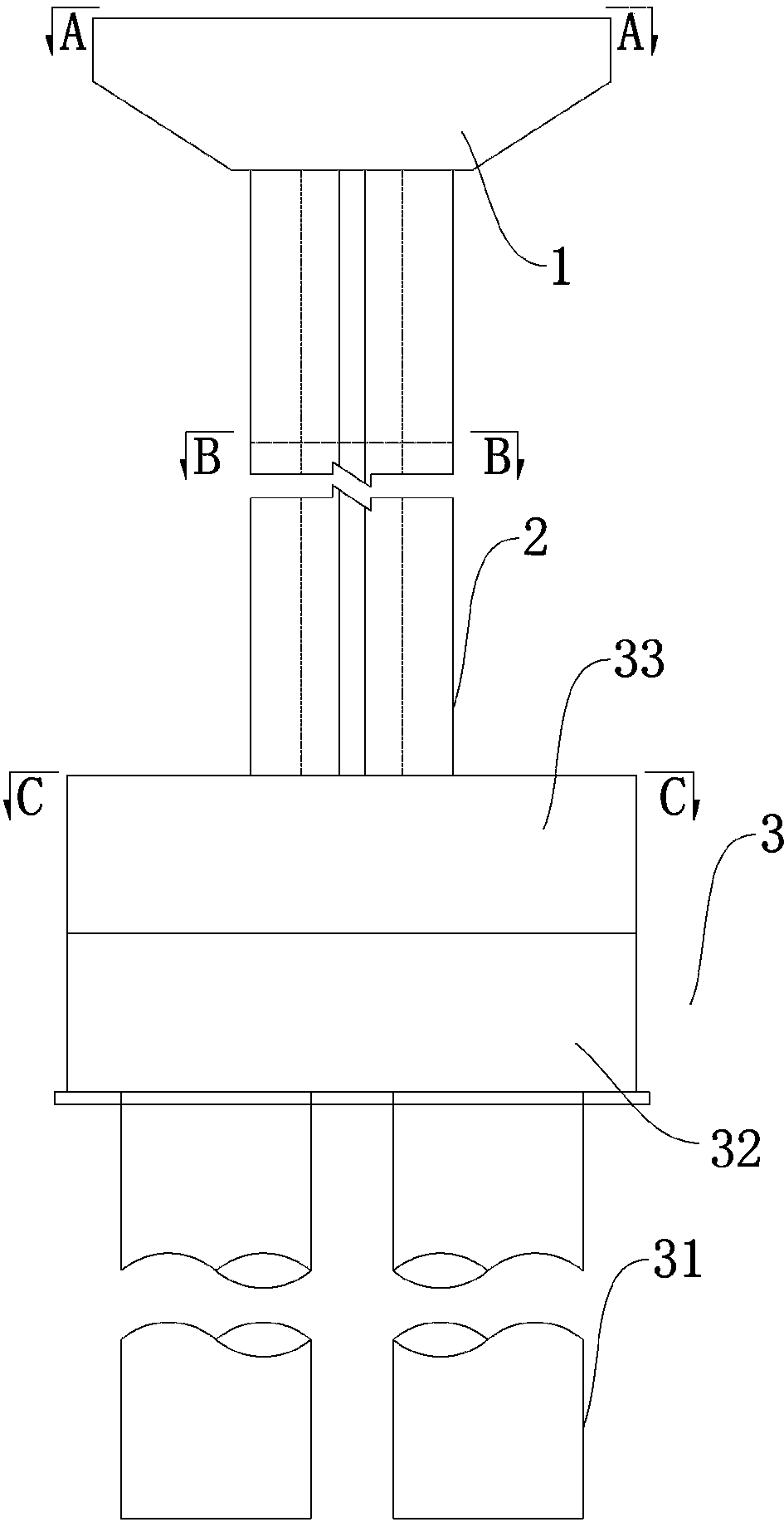
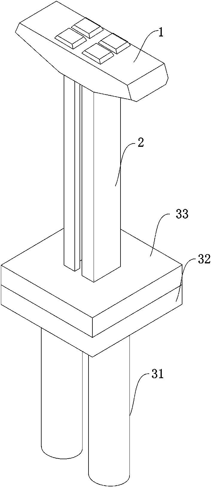
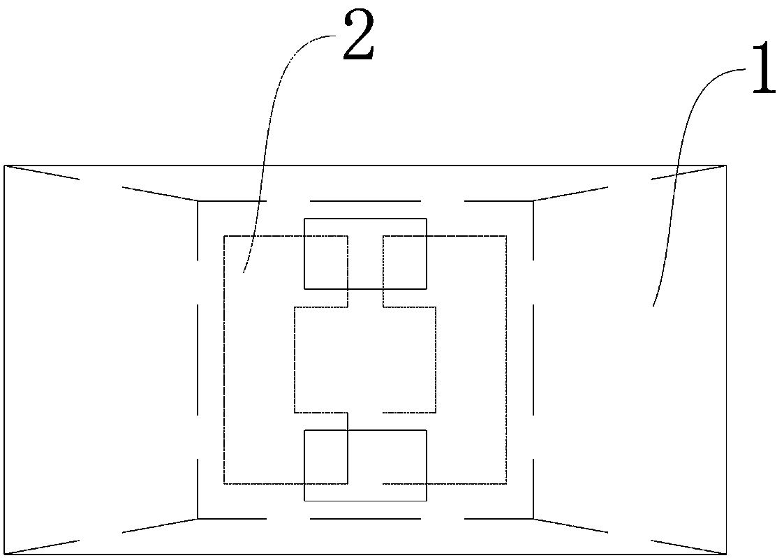
The invention discloses a double-limb thin-wall T-shaped pier which comprises a bearing platform base, U-shaped columns and a bent cap. The U-shaped columns are arranged between the bearing platform base and the bent cap in pairs, and staggered openings of the U-shaped columns are oppositely formed to form hollow thin-wall pier columns. The double-limb thin-wall T-shaped pier has the beneficial effects that the double-limb thin-wall T-shaped pier is split into the bent cap and the two U-shaped columns, the bent cap and the two U-shaped columns are prefabricated and machined in a factory through mechanical line production, the U-shaped columns can be prefabricated in a supine mode and are convenient to manufacture, store and transport, and the integral double-limb thin-wall T-shaped pier can be assembled in the factory. The bent cap and the U-shaped columns are disassembled, prefabricated and assembled into the hollow component, so that the structural strength of the hollow component isguaranteed, and 30-40% of raw materials are saved. During on-site installation, mechanical hoisting can be adopted, the on-site operation time is less than 3 days, and the on-site operation time is greatly shortened compared with that of an original cast-in-place pier stud bent cap which needs to be operated for more than 25 days, so that the time of road traffic and urban environment influence is reduced.

Description

technical field [0001] The invention relates to the technical field of bridge construction, in particular to a double-leg thin-walled T-shaped pier. Background technique [0002] The pier is mainly composed of a top hat or hat beam and a pier body. The abutment is mainly composed of a top hat and an abutment body. The function of the top hat or hat beam is to transfer the large and concentrated force transmitted from the bridge span support to the pier body and platform body in a dispersed and uniform manner, so the top hat has a higher strength requirement. In addition, the top hat and the hat beam must have a larger plane size to provide the necessary working surface for the construction of the beam and maintenance and repair. The pier body and abutment body are the main structures supporting the bridge span, not only bear all the loads from the bridge span structure, but also directly bear various loads such as earth pressure, water impact force, ice pressure, ship impa...

Claims


Application Information

Patent Timeline
Patent Type & Authority Applications(China)
IPC IPC(8): E01D19/02
CPCE01D19/02
Inventor 赵晓波陈波韦登厚郭宏飞沈中原张富贵权志杰周胜怡
Owner 重庆单轨交通工程有限责任公司
Learn More