
Multifunctional mechanical pump

A multi-functional machine and impeller technology, applied in the field of mechanical pumps, can solve problems such as shaking, affecting the normal use of the rotating shaft, and expensive pumps, and achieve the effects of stable rotation, reliable performance, and improved transmission efficiency

Pending Publication Date: 2017-12-15
东莞客能机械泵业有限公司
View PDF6 Cites 1 Cited by
  • Summary
  • Abstract
  • Description
  • Claims
  • Application Information

AI Technical Summary

Problems solved by technology

Current impeller pumps are usually only used to pump clean water or fluids with low viscosity
However, fluids with high viscosity, such as mud in the ceramic industry or other industries, require special pumps, which are expensive and cost a lot of money for enterprises.
The ordinary impeller pump has a certain frictional resistance due to the cooperation between the shaft and the shaft sleeve, and when the speed is too high, there will be shaking problems, which will affect the normal use of the shaft. Therefore, the current general impeller pump cannot be used Pumping operations for more viscous fluids

Method used


Image

  • Multifunctional mechanical pump
  • Multifunctional mechanical pump
  • Multifunctional mechanical pump

Examples


Embodiment Construction

[0017] In order to further understand the features, technical means, and specific objectives and functions achieved by the present invention, the present invention will be further described in detail below in conjunction with the accompanying drawings and specific embodiments.

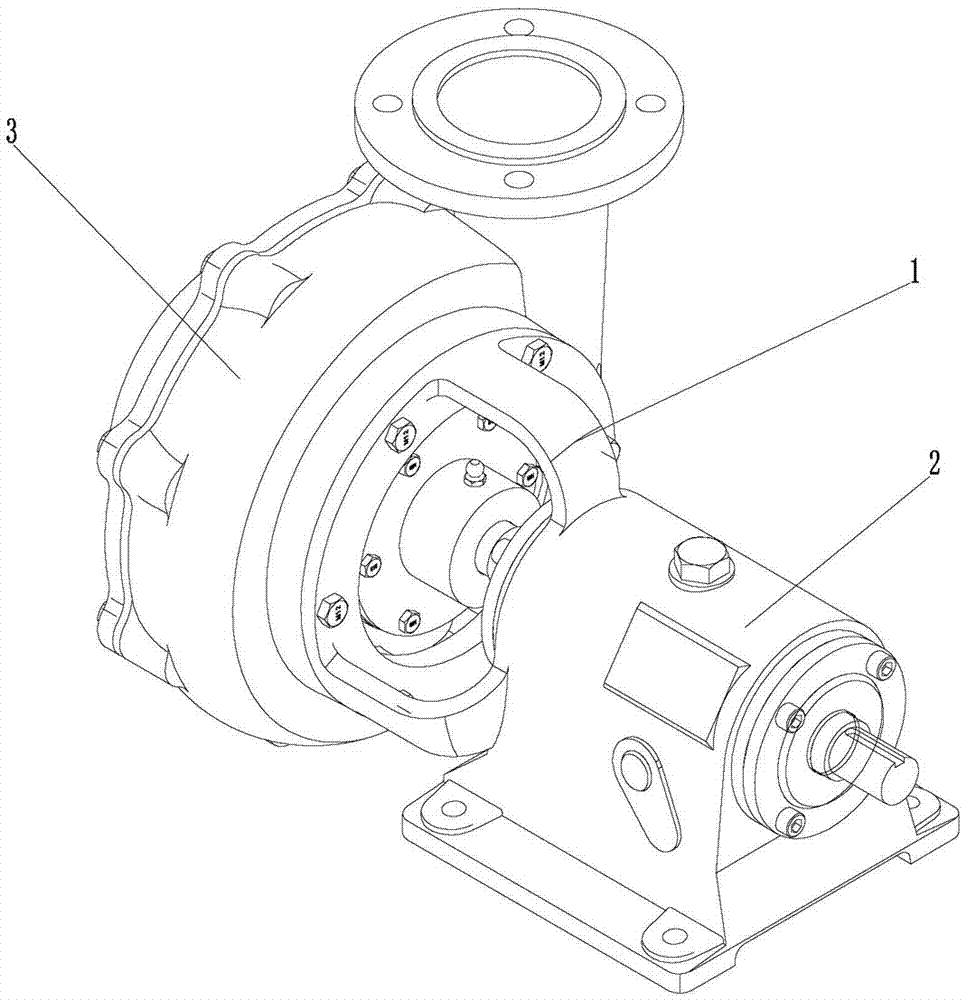
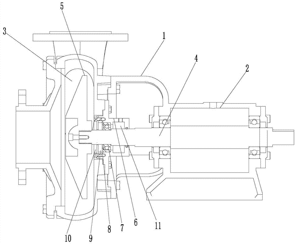
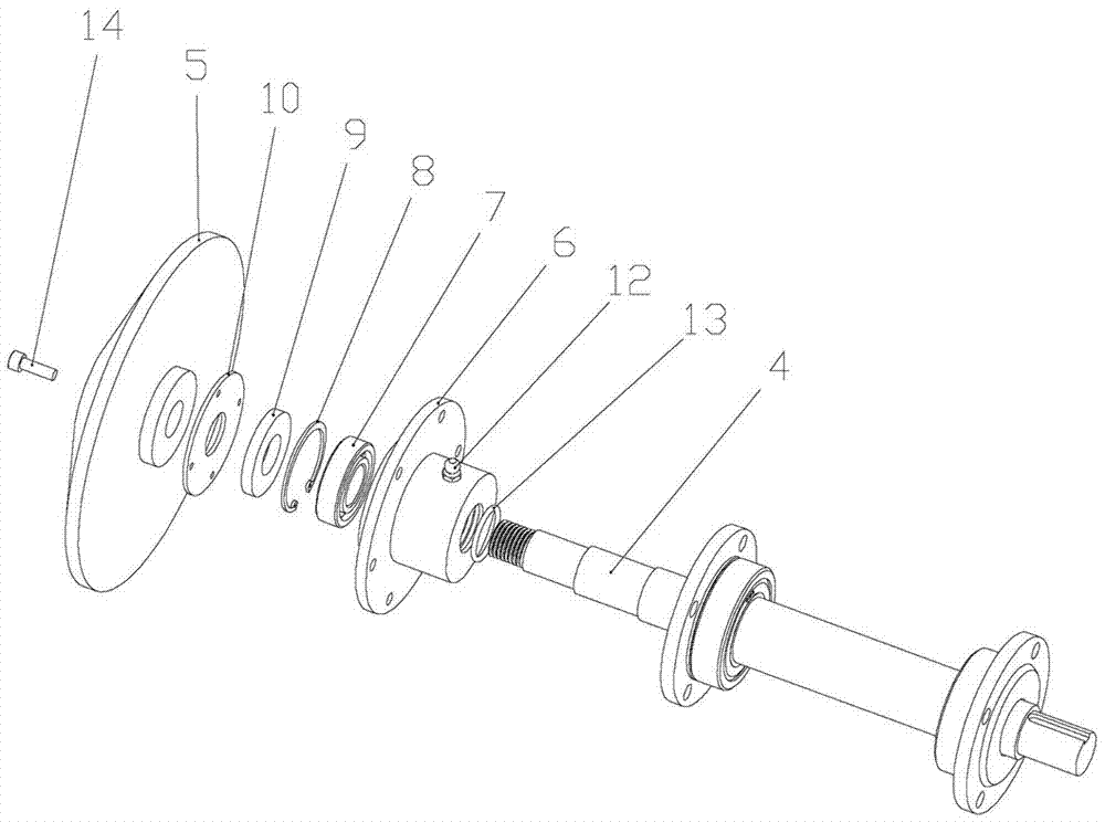
[0018] as attached Figure 1-4 As shown, the present invention discloses a multifunctional mechanical pump, comprising a housing 1, an impeller 5, a rotating shaft 4 and a motor 2, the impeller 5 is installed in the housing 1, the rotating shaft 4 is connected to the motor 2, and the housing 1 is provided with The impeller installation chamber 3, the impeller 5 is installed in the impeller installation chamber 3, the housing 1 is fixedly installed with the installation part 6 between the impeller 5 and the motor 2, the installation part 6 is installed with a fixed bearing 7, the installation part 6 There is a sealing ring 9 sealing the fixed bearing 7 inside, and the port of the mounting part 6 is inst...


PUM


Abstract

The invention relates to a multifunctional mechanical pump. The multifunctional mechanical pump comprises a shell, an impeller, a rotating shaft and a motor; the impeller is installed in the shell, the rotating shaft is connected with the motor, an impeller installing cavity is arranged in the shell, the impeller is installed in the impeller installing cavity, an installing piece located between the impeller and the motor is fixedly installed in the shell, a fixed bearing is installed in the installing piece, and a sealing ring for sealing the fixed bearing is arranged in the installing piece; the position where the installing piece is fixed is further provided with a sealing cover for sealing the sealing ring and the fixed bearing into the installing piece, and the front end of the rotating shaft extends into the installing piece, sequentially penetrates the fixed bearing, the sealing ring and the sealing cover, enters the impeller installing cavity and is fixedly connected with the impeller; and the installing piece and the shell are of an integrated structure, or the installing piece is a fixed flange. The multifunctional mechanical pump is high in rotating speed and reliable in performance, the problems about high temperature grease cooling and superconduction lubrication which are generated by high-speed rotation are solved, external force friction is avoided, and the multifunctional mechanical pump is suitable for pipe conveying with particular liquid, dense slurry, dry aggregates and clean water.

Description

technical field [0001] The invention relates to a mechanical pump, in particular to a multifunctional mechanical pump which can be widely used for pumping clear water, mud and the like. Background technique [0002] The impeller pump drives the liquid to rotate at high speed through the working impeller, and transfers the mechanical energy to the liquid, so as to achieve the purpose of conveying the liquid. Impeller pumps include: centrifugal, mixed flow, axial flow, and vortex. The existing impeller pump includes an impeller connected with a rotating shaft, one end of the rotating shaft is connected with the motor, and the other end is clamped on the pump casing through a shaft sleeve. Current impeller pumps are usually only used for pumping clean water or fluids with low viscosity. However, fluids with high viscosity, such as mud in the ceramic industry or other industries, require special pumps, which are expensive and cost a lot of money for enterprises. The ordinary ...

Claims


Application Information

Patent Timeline
Patent Type & Authority Applications(China)
IPC IPC(8): F04D13/06F04D7/04F04D29/046F04D29/66F04D29/58F04D29/06F04D29/08
CPCF04D7/04F04D13/06F04D29/046F04D29/061F04D29/086F04D29/586F04D29/669
Inventor 黄伟平
Owner 东莞客能机械泵业有限公司
Learn More