A pavement structural mechanical behavior testing device and method

A technology of pavement structure and test device, which is applied in soil material testing, material inspection products, etc., can solve the problems of high consumption of manpower and material resources, limited test results, poor controllability, etc., and achieve the effect of ensuring accuracy

Inactive Publication Date: 2017-12-15
CHANGAN UNIV
View PDF5 Cites 11 Cited by
  • Summary
  • Abstract
  • Description
  • Claims
  • Application Information

AI Technical Summary

Problems solved by technology

[0006] In view of the deficiencies in the prior art, the object of the present invention is to provide a test device and test method for the mechanical behavior of pavement structure

Method used


Image

  • A pavement structural mechanical behavior testing device and method
  • A pavement structural mechanical behavior testing device and method
  • A pavement structural mechanical behavior testing device and method

Examples


Embodiment 1

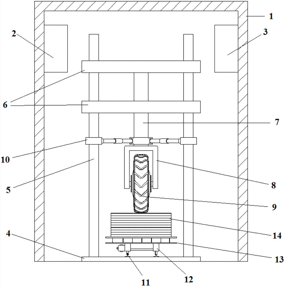
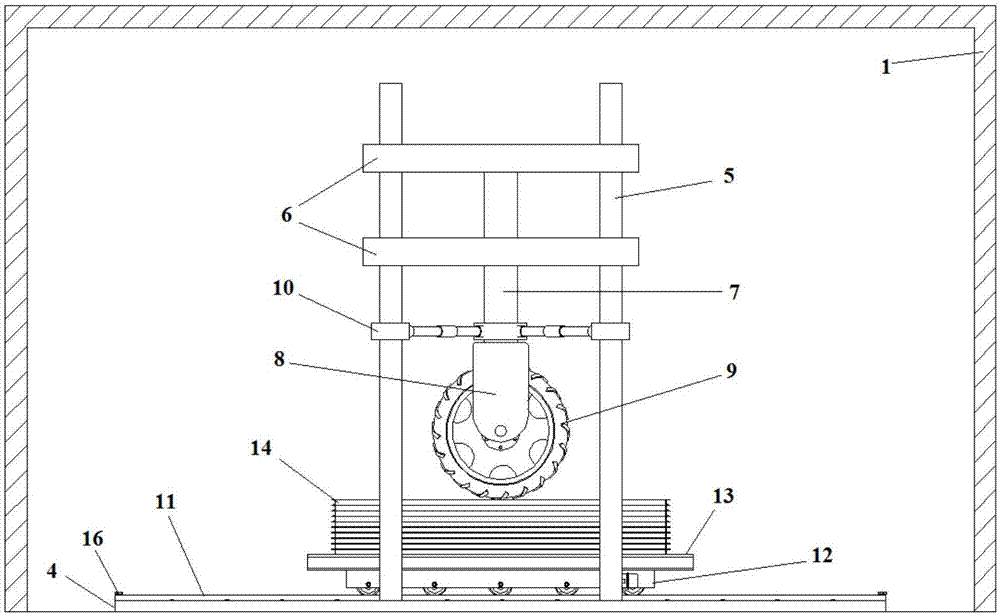
[0063] Such as Figure 1 to Figure 11 As shown, the present embodiment provides a test device for the mechanical behavior of pavement structures, including a thermal insulation room 1, a temperature control system 2 and a humidity control system 3 are installed in the thermal insulation room 1, and a base 4 is provided at the bottom of the thermal insulation room 1. 4 is provided with a group of columns 5 around, and the lifting platform 6 that can lift on the column 5 is installed on the column 5, and the telescopic oil cylinder 7 stretching out the bottom of the lifting platform 6 is installed on the lifting platform 6, and the telescopic oil cylinder 7 is vertically arranged with the base 4, The bottom end of telescopic oil cylinder 7 is provided with loading mechanism 8, and tire 9 is installed on loading mechanism 8;

[0064] The tire positioning mechanism 10 is installed on the column 5 and the telescopic oil cylinder 7, and the tire positioning mechanism 10 includes a c...

Embodiment 2

[0082] This embodiment provides a method for testing the mechanical behavior of pavement structures. The method uses the test device for the mechanical behavior of pavement structures described in Example 1, and specifically includes the following steps:

[0083] Step 1, preliminary preparation:

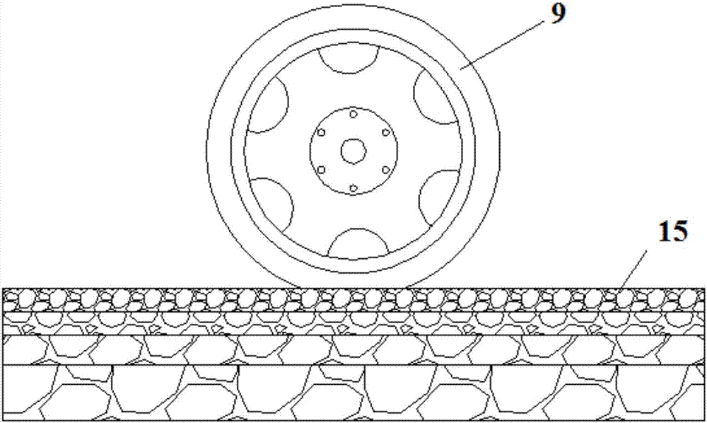
[0084] For the pavement structure to be studied, the preliminary calculation of pavement mechanics is used to determine the key damage area of ​​the pavement structure and the restraint stiffness of this area. The stiffness of the sample box 14 and the support platform 13 is fine-tuned to ensure that the constraint stiffness of the critical damage area is consistent with the actual road surface;

[0085] Step 2, sample making:

[0086] On the basis of step one, the determined sample box 14 and support platform 13 are installed on the wheel box 12 , and the wheel box 12 is installed on the guide rail 11 . Vibration and compaction method is adopted to make pavement material and the p...


PUM


Abstract

A pavement structural mechanical behavior testing device and method are provided. The bottom inside an insulating building is provided with a pedestal. The pedestal is provided with a group of vertical pillars. Lifting and descending platforms capable of being lifted and descending along the vertical pillars are mounted to the vertical pillars. A telescopic cylinder protruding out of the bottoms of the lifting and descending platforms is mounted to the lifting and descending platforms, and is perpendicular to the pedestal. The bottom of the telescopic cylinder is provided with a loading mechanism. A tyre is mounted to the loading mechanism. The vertical pillars and the telescopic cylinder are provided with a tyre positioning mechanism. A pair of guide rails are paved on the pedestal below the tyre. A roller box moving along the guide rails is mounted on the guide rails. A supporting platform is mounted to the top surface of the roller box. A test specimen box used for accommodating a pavement test specimen is mounted on the top surface of the supporting platform. According to the device and the method, restraint functions of pavement surrounding structures to critical damage zones are simulated by adopting a steel structure, and therefore the restraint state of pavement surrounding structures to critical damage zones in natural environment of an actual pavement can be simulated furthest.

Description

technical field [0001] The invention belongs to the field of pavement structural mechanics, and relates to the research on mechanical behavior and long-term durability of pavement structure, in particular to a test device and test method for pavement structural mechanical behavior. Background technique [0002] Road transportation plays an important role in the development of the national economy. Under the cyclic action of vehicle loads and environmental loads, damage to the pavement structure accumulates, resulting in various diseases, such as cracks, rutting, etc. These pavement diseases not only affect the driving comfort and safety of vehicles, reduce road service performance, but also affect Service life of pavement structures. Therefore, it is particularly important to study the mechanical behavior of pavement structures under vehicle loads and environmental loads. [0003] At present, the commonly used test methods for the mechanical behavior of pavement structures...

Claims


Application Information

Patent Timeline
IPC IPC(8): G01N33/24
CPCG01N33/24
Inventor 董忠红郭志勇荣明达吴学前
Owner CHANGAN UNIV
Why Eureka
Try Eureka