
Non-paraxial self-accelerating beam generation method based on angular spectrum regulation and control and non-paraxial self-accelerating beam generation device thereof

A production method and self-accelerating technology, applied in optics, optical components, microscopes, etc., to achieve the effect of simple theoretical realization, easy implementation and wide application range

Active Publication Date: 2017-12-15
XI'AN INST OF OPTICS & FINE MECHANICS - CHINESE ACAD OF SCI
View PDF6 Cites 6 Cited by
  • Summary
  • Abstract
  • Description
  • Claims
  • Application Information

AI Technical Summary

Problems solved by technology

[0006] For more complex beam requirements in actual needs, there is still no common method to realize self-accelerating beams with complex curved trajectories according to actual needs.

Method used


Image

  • Non-paraxial self-accelerating beam generation method based on angular spectrum regulation and control and non-paraxial self-accelerating beam generation device thereof
  • Non-paraxial self-accelerating beam generation method based on angular spectrum regulation and control and non-paraxial self-accelerating beam generation device thereof
  • Non-paraxial self-accelerating beam generation method based on angular spectrum regulation and control and non-paraxial self-accelerating beam generation device thereof

Examples


Embodiment 1

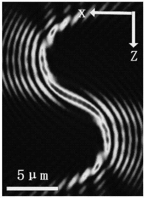
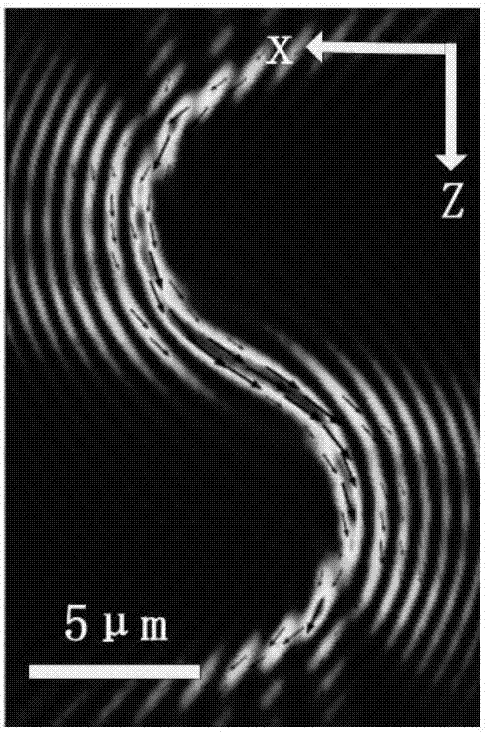
[0055] This embodiment provides a method for generating a non-paraxial self-accelerating beam with an S-shaped curved propagation trajectory, which mainly includes the following steps:

[0056] Using the angular spectrum expansion to describe the non-paraxial self-accelerating beam with S-shaped curved propagation trajectory:

[0057]

[0058] Among them, E SHB (x, y, z) is the two-dimensional electric field of a non-paraxial self-accelerating beam with an S-shaped curved propagation trajectory polarized along the y-axis, is the angular spectrum function, k z is the wave vector, (x, y, z) is the coordinate describing a point in the light field in the Cartesian coordinate system, describes the azimuth angle;

[0059] The angular spectral function is obtained by linearly superimposing the angular spectral functions of multiple self-accelerating sub-beams

[0060]

[0061] in, is the existing self-accelerating sub-beam, here select the half-Bessel self-acceleratin...

Embodiment 2

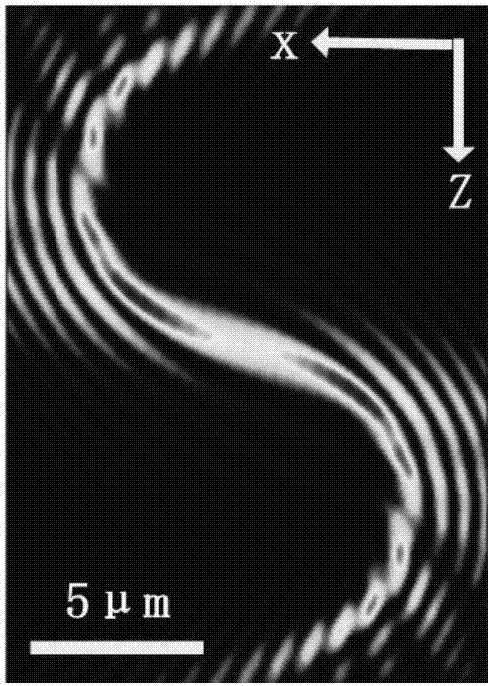
[0072] In the specific implementation of generating a self-accelerating beam with an S-shaped propagation trajectory, there are different degrees of discontinuous spots at the incident end and the output end of the beam, such as figure 1 shown. Although the tail and side lobe effects of the non-paraxial self-accelerating light field are very weak and will not affect the experimental results, but in order to better design and apply the S-type non-paraxial self-accelerating light field and improve the experimental accuracy, the apodization function Introduce the light field control of complex trajectories to achieve further optimization of the light field. At the same time, based on the idea of ​​angular spectrum control, the spectrum control of the beam bending angle can also be realized to optimize the beam.

[0073] This embodiment further introduces the apodization function on the basis of embodiment 1 Optimizing the light field, the angular spectrum expansion E of the ...


PUM


Abstract

The invention belongs to the technical field of beam regulation and control, and particularly relates to a non-paraxial self-accelerating beam generation method based on angular spectrum regulation and control and a non-paraxial self-accelerating beam generation device thereof. The non-paraxial self-accelerating beam generation method based on angular spectrum regulation and control comprises the following steps that 1) the angular spectrum function of self-accelerating sub-beams is regulated and controlled and linearly superposed; 2) displacement regulation and control parameters deltax and deltaz are regulated so as to realize redistribution of the intensity of the light field along bent trajectories; and 3) the angular spectrum function A(theta,phi) is loaded to the angular spectrum expansion equation of the non-paraxial self-accelerating beam so as to obtain the non-paraxial self-accelerating beam having the bent propagation trajectories. The limitation of the paraxial approximation conditions can be overcome through angular spectrum regulation and control, and the bent self-accelerating beam of any angle can be theoretically realized.

Description

technical field [0001] The invention belongs to the technical field of beam regulation, and in particular relates to a non-paraxial self-accelerating beam generation method and generation device based on angular spectrum regulation. Background technique [0002] The unique dynamic characteristics of self-bending, non-diffraction, and self-healing propagation go against people's cognition of the "eternal invariability" of beam propagation along a straight line, and at the same time make self-accelerating beams gradually develop into a research hotspot in new types of light fields , and has been rapidly applied in the fields of optical micro-manipulation, optical microscopy and super-resolution imaging, plasmonic channels and surface plasmons. With the promotion and deepening of theoretical research and related application research on self-bending beams, more complex and practical requirements have been put forward for the propagation trajectory of beams. According to actual n...

Claims


Application Information

Patent Timeline
IPC IPC(8): G02B27/00G03H1/22G02B21/36
CPCG02B21/361G02B27/0012G03H1/2294
Inventor 韩国霞姚保利黄张翔张鹏
Owner XI'AN INST OF OPTICS & FINE MECHANICS - CHINESE ACAD OF SCI
Learn More