Diffraction device

A diffractive device and diffractive lens technology, applied in the field of diffractive lenses, can solve problems such as simple functions

Pending Publication Date: 2017-12-15
BOE TECH GRP CO LTD
View PDF6 Cites 20 Cited by
  • Summary
  • Abstract
  • Description
  • Claims
  • Application Information

AI Technical Summary

Problems solved by technology

However, the disadvantages of the existing lenses are that the functions are simple, the diffraction effect and the focal length are fixed, and cannot be flexibly changed according to needs

Method used


Image

  • Diffraction device
  • Diffraction device
  • Diffraction device

Examples


Embodiment Construction

[0042] The present invention will be described in detail below in conjunction with the accompanying drawings.

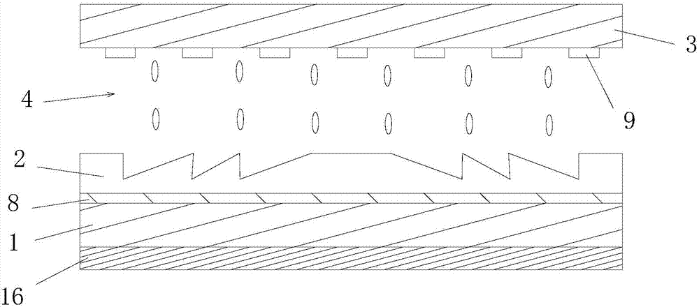
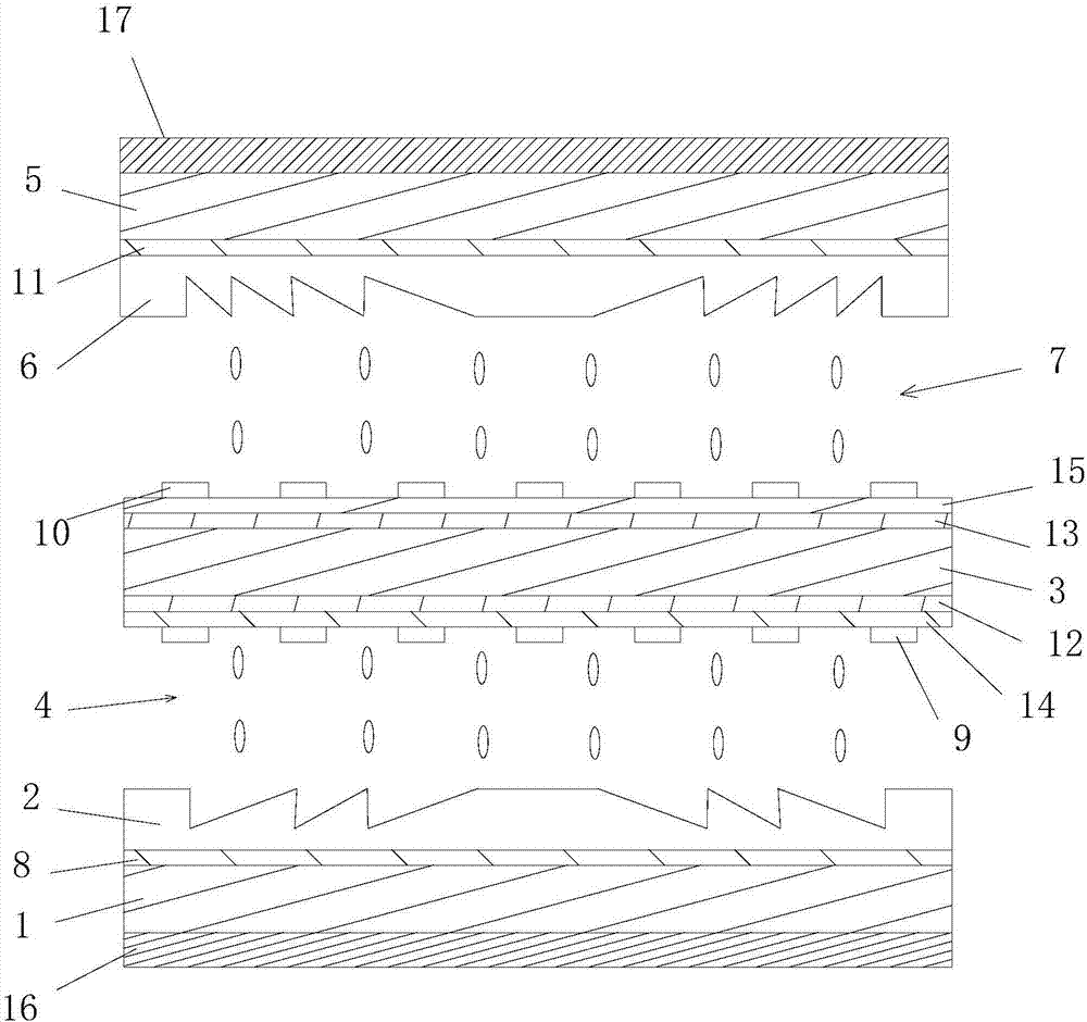
[0043] Such as figure 1 and figure 2 As shown, the present invention provides a kind of diffraction device, comprises the first diffraction unit, and this first diffraction unit comprises:

[0044] The first substrate 1 is provided with a first polarizer 16 on one side and a first electrode 8 on the other side;

[0045] The first diffractive lens 2, which is arranged on the first electrode 8;

[0046] A second substrate 3, which is arranged opposite to the first substrate 1, and a second electrode 9 is provided on the side of the second substrate 3 facing the other side of the first substrate 1; and

[0047]The first liquid crystal layer 4 is arranged between the second electrode 9 and the first diffractive lens 2. When the first electrode 8 and the second electrode 9 are energized, a vertical first liquid crystal layer is generated between the first electrode 8 ...


PUM


Abstract

The invention provides a diffraction device which comprises a first diffraction unit. The first diffraction unit comprises a first substrate, a first diffraction lens, a second substrate and a first liquid crystal layer, wherein a first polaroid is arranged on one side of the first substrate, and a first electrode is arranged on the other side of the first substrate; the first diffraction lens is arranged on the first electrode; the second substrate is opposite to the first substrate, and a second electrode is arranged on the side, opposite to the other side of the first substrate, of the second substrate; the first liquid crystal layer is arranged between the second electrode and the first diffraction lens, liquid crystals in the first liquid crystal layer can be in the state that the long axis direction of the liquid crystals is parallel to the axial direction of the optical axis of the first polaroid or the state that the long axis direction of the liquid crystals is perpendicular to the axial direction of the optical axis of the first polaroid. The diffraction device is provided with a plurality of diffraction units which can convert diffraction modes according to different external electric fields, and the working modes of the multiple diffraction units can be converted freely according to user's needs.

Description

technical field [0001] The invention relates to the field of diffraction lenses, in particular to a diffraction device. Background technique [0002] Lens is a basic optical device, which can be seen everywhere in optical equipment. With the development of optical technology, the requirements for lenses are getting higher and higher. For example, the shape of the lens ranges from spherical to aspherical, especially the cylinder and parabola are the most widely used; there are also requirements for the volume and weight of the lens, such as the Fresnel lens, which is small in size, light in weight, and easy to use. It is widely used due to its advantages such as replication. But the disadvantage of the existing lens is that the function is simple, the diffraction effect and the focal length are fixed, and cannot be flexibly changed according to the needs. Contents of the invention [0003] The problem to be solved by the present invention is to provide a diffraction devic...

Claims


Application Information

Patent Timeline
Patent Type & Authority Applications(China)
IPC IPC(8): G02F1/1335
CPCG02F1/133526G02F1/133528G02F1/292G02F1/13471G02F1/134372G02F1/294G02F1/137G02F1/13362G02F1/134309
Inventor 高健陈小川王维谭纪风孟宪东
Owner BOE TECH GRP CO LTD
Why Eureka
Try Eureka