Self-powered switch

A self-powered and switching technology, applied in electrical switches, circuits, electrical components, etc., can solve the problem of difficult fixing of micro power generation devices, and achieve the effect of simple structure and improved reliability.

Active Publication Date: 2017-12-15
一冷豪申新能源(上海)有限公司
View PDF9 Cites 1 Cited by
  • Summary
  • Abstract
  • Description
  • Claims
  • Application Information

AI Technical Summary

Problems solved by technology

[0007] According to the technical solution provided by the embodiment of the present application, the magnet group is rotatably fixed by the second magnet group fixing component, which ensures the normal operation of the miniature power generation device in the self-powered switch, and at the same time can fix the magnet group, which improves the reliability of the self-powered switch. The structure is simple, through the first spring strut, the circuit is turned on and off during the key swing process, and the circuit is controlled, which can solve the problem that the micro power generation device in the self-powered switch is not easy to fix, including the substrate body, the substrate body It is set as a shell with one end open, the bottom surface of the substrate body is provided with a first magnet group fixing assembly, the first magnet group fixing assembly is provided with a first fixing plate and a second fixing plate oppositely arranged, and the first fixing plate is provided with a first Through holes, the second fixed plate is provided with a second through hole, the first fixed plate is provided with a first protrusion on the side away from the second fixed plate, and the second fixed plate is provided with a second protrusion on the side away from the first fixed plate The opposite sides of the substrate are respectively provided with card interfaces, the two ends of the first magnet group fixing component are oppositely provided with a card connecting plate, and the side of the card connecting plate facing the first magnet group fixing component is provided with a card connecting protrusion

Method used


Image

  • Self-powered switch
  • Self-powered switch
  • Self-powered switch

Examples


Embodiment Construction

[0013] The application will be further described in detail below in conjunction with the accompanying drawings and embodiments. It should be understood that the specific embodiments described here are only used to explain related inventions, rather than to limit the invention. It should also be noted that, for ease of description, only parts related to the invention are shown in the drawings.

[0014] It should be noted that, in the case of no conflict, the embodiments in the present application and the features in the embodiments can be combined with each other. The present application will be described in detail below with reference to the accompanying drawings and embodiments.

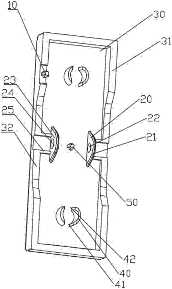
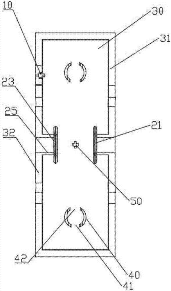
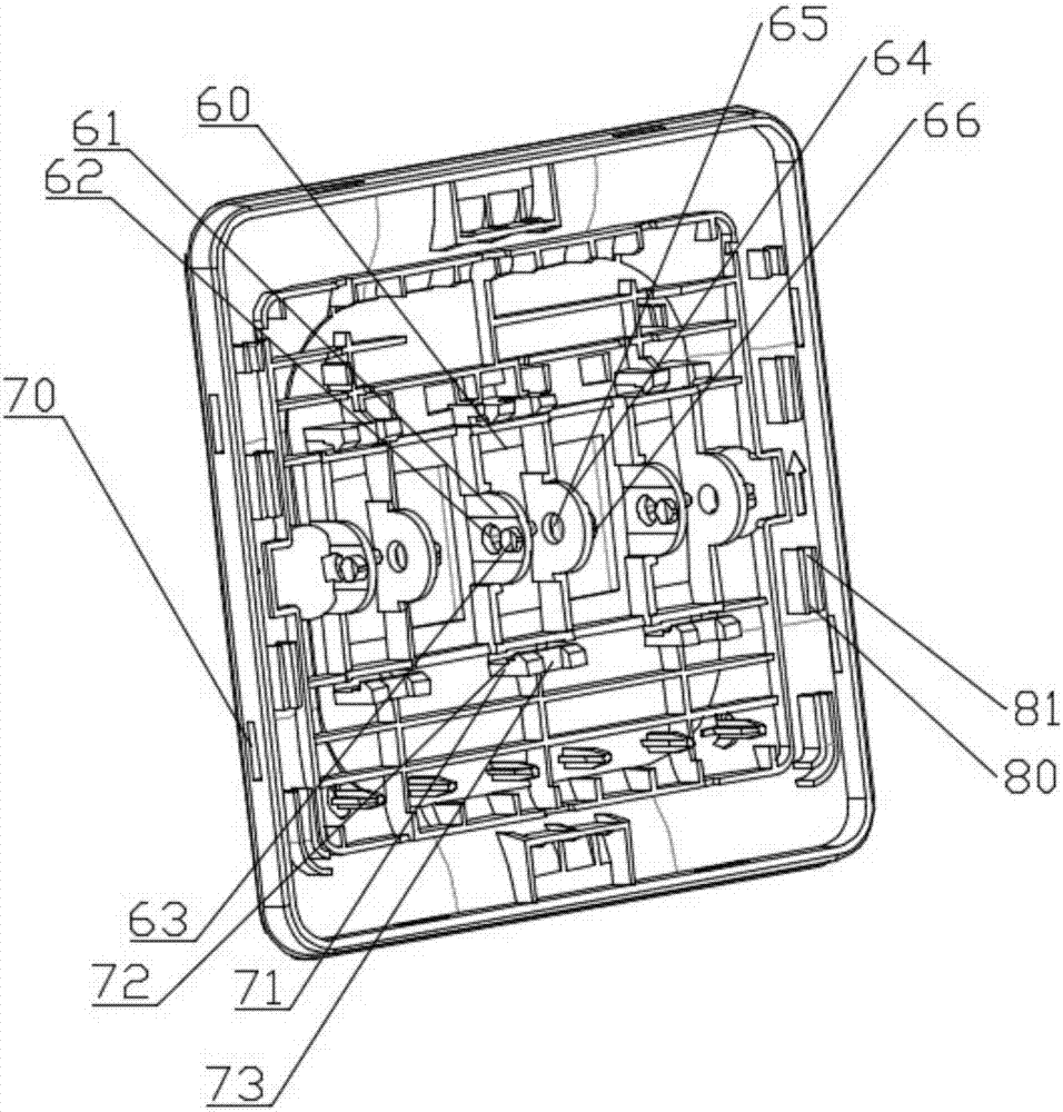
[0015] Please refer to figure 1 with figure 2 , the self-powered switch of the present invention includes a button body, the button body is fixed with a first spring strut 10 and a second magnet group fixing assembly 20, and the second magnet group fixing assembly 20 is provided with a third fix...


PUM


Abstract

The present application discloses a self-powered switch comprising a key body and a substrate body. The key body is fixed with a first spring post and a second magnet group fixing component; the second magnet group fixing component is provided with third fixing plates and second fixing plates arranged at intervals. The third fixing plates are provided with third fixing holes; the second fixing plates are provided with fourth fixing holes. Both ends of the key body away from the second magnet group fixing component are set as wobble ends, with the first spring post disposed between the wobble ends and the second magnet group fixing component, which improves the reliability of the self-powered switch. The switch is simple in structure. Through the first spring post, it is possible to realize the power-on and power-off of the circuit during the swing process of the key; and therefore, the control over the circuit solves the problem that the micro power generation device in the self-powered switch cannot be fixed easily.

Description

technical field [0001] The present disclosure generally relates to the field of the Internet of Things, specifically to the field of self-powered switches, and in particular to a self-powered switch. Background technique [0002] With the development of the national economy, people's living standards are gradually improving, so the requirements for life convenience, energy conservation and environmental protection are also getting higher and higher. High-tech wireless electronic products bring convenience to people's lives, but electronic products must have power to work. Batteries are commonly used as power sources at present, but the batteries have many limitations, and the limited service life requires repeated replacement of the batteries, which increases the cost of use. There are potential safety hazards during battery use, such as rust or liquid leakage. Battery production consumes resources, and waste pollutes the environment. Some special occasions are not suitab...

Claims


Application Information

Patent Timeline
Patent Type & Authority Applications(China)
IPC IPC(8): H01H13/10H02K35/02
CPCH01H13/10H02K35/02
Inventor 吴义王大庆
Owner 一冷豪申新能源(上海)有限公司
Why Eureka
Try Eureka